
 HONG KONG SAUL

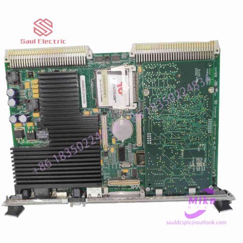
DS200ADMAH1AAA Mark VIe Control System
DS200ADMAH1AAA Product Introduction
Basic Information
Brand: GE (General Electric)
Model:DS200ADMAH1AAA
Part Number: DS200ADMAH1AAA
Series: Mark VIe Speedtronic Turbine Control System I/O Pack
Country of Origin: United States
Product Type: Discrete Input Module (Contact Input Module), also known as PDIA I/O Pack
 Functional Overview
The DS200ADMAH1AAA is a 24-channel discrete (digital) input module in the GE Mark VIe control system. Its primary function is to collect discrete signals (contact open/close signals) generated by field devices such as sensors,
switches, and relays, convert them into digital signals that can be recognized and processed by the PLC or control system CPU,
and transmit the processed data to the GE Speedtronic turbine control system or other control equipment, enabling automated control and monitoring. Key Technical Specifications
Rated Voltage: 24.0 VDC (Nominal)
Maximum Rated Voltage: 28.6 VDC
Maximum Rated Contact Input Voltage: 32 VDC
Number of Input Channels: 24 Discrete Inputs
Operating Temperature Range: -30°C to +65°C
Environmental Adaptability: Passes rigorous environmental testing, capable of long-term stable operation in harsh industrial environments Compatible Terminal Boards
The DS200ADMAH1AAA can be paired with a variety of GE terminal boards, including but not limited to:
IS200STCIH1A / IS200STCIH2A
IS200STCIH8A
IS200TBCIH2C / IS200TBCIH4C
IS400STCIH1A / IS400STCIH2A / IS400STCIH8A
IS400TBCIH2C Certifications and Safety
This module is UL certified and can be used in both hazardous and non-hazardous locations. The UL certification covers various classes and divisions, and relevant UL mark documents are available for reference.
Four-wire resistive screen
The four-wire resistive screen is covered with two layers of transparent conductive layer ITO (ITO: indium oxide, weak conductor) between the surface protective coating and the base layer. The characteristic is that when the thickness drops below 1800 angstroms (angstroms = 10-10 meters) It will suddenly become transparent, and the light transmittance will decrease when it gets thinner. When the thickness reaches 300 angstroms, the light transmittance will increase again. It is the main material of all resistive screens and capacitive screens.), the two layers correspond to the X and Y axes respectively. They are They are insulated with fine transparent insulating particles. When touched, the pressure generated connects the two conductive layers. Due to the change in resistance value, the X and Y coordinates of the touch are obtained.
Five-wire resistive screen
The base layer of the five-wire resistive screen is covered with a transparent conductive layer ITO that adds voltage fields in the X and Y directions to the same layer. The outermost nickel-gold conductive layer (nickel-gold conductive layer: the outer conductive layer of the five-wire resistive touch screen The outer conductive layer uses a nickel-gold coating material with good ductility. Due to frequent touching, the purpose of using a nickel-gold material with good ductility is to extend the service life.) It is only used as a pure conductor. When touching, use a The position of the touch point is measured by detecting the X-axis and Y-axis voltage values of the contact point. The inner layer ITO requires four leads and the outer layer one, for a total of 5 leads.
capacitive screen
The surface of the capacitive screen is coated with a transparent conductive layer of ITO, and the voltage is connected to the four corners. Tiny DC current dissipates on the screen surface, forming a uniform electric field. When the screen is touched by hand, the human body acts as one pole of the coupling capacitor, and the current collects from the four corners of the screen to form another coupling capacitor. On one pole, the controller calculates the relative distance from the current to the touch location to obtain the coordinates of the touch.
Infrared screen
The infrared touch screen uses a dense infrared matrix in the X and Y directions to detect and locate the user’s touch. The infrared touch screen installs a circuit board frame in front of the display. The circuit board arranges infrared transmitting tubes and infrared receiving tubes on the four sides of the screen, corresponding to each other to form a horizontal and vertical infrared matrix. When a user touches the screen, his or her finger will block the horizontal and vertical infrared rays passing through that location, so the location of the touch point on the screen can be determined. Any touching object can change the infrared rays on the contact points to achieve touch screen operation.

There are no reviews yet.