
 HONG KONG SAUL
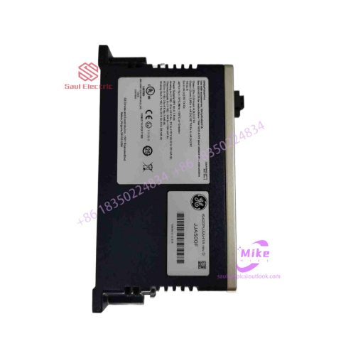
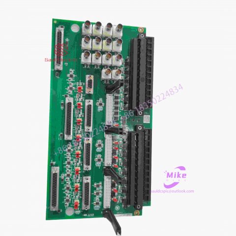
DS200DENCF1ACH Mark VIe Control System
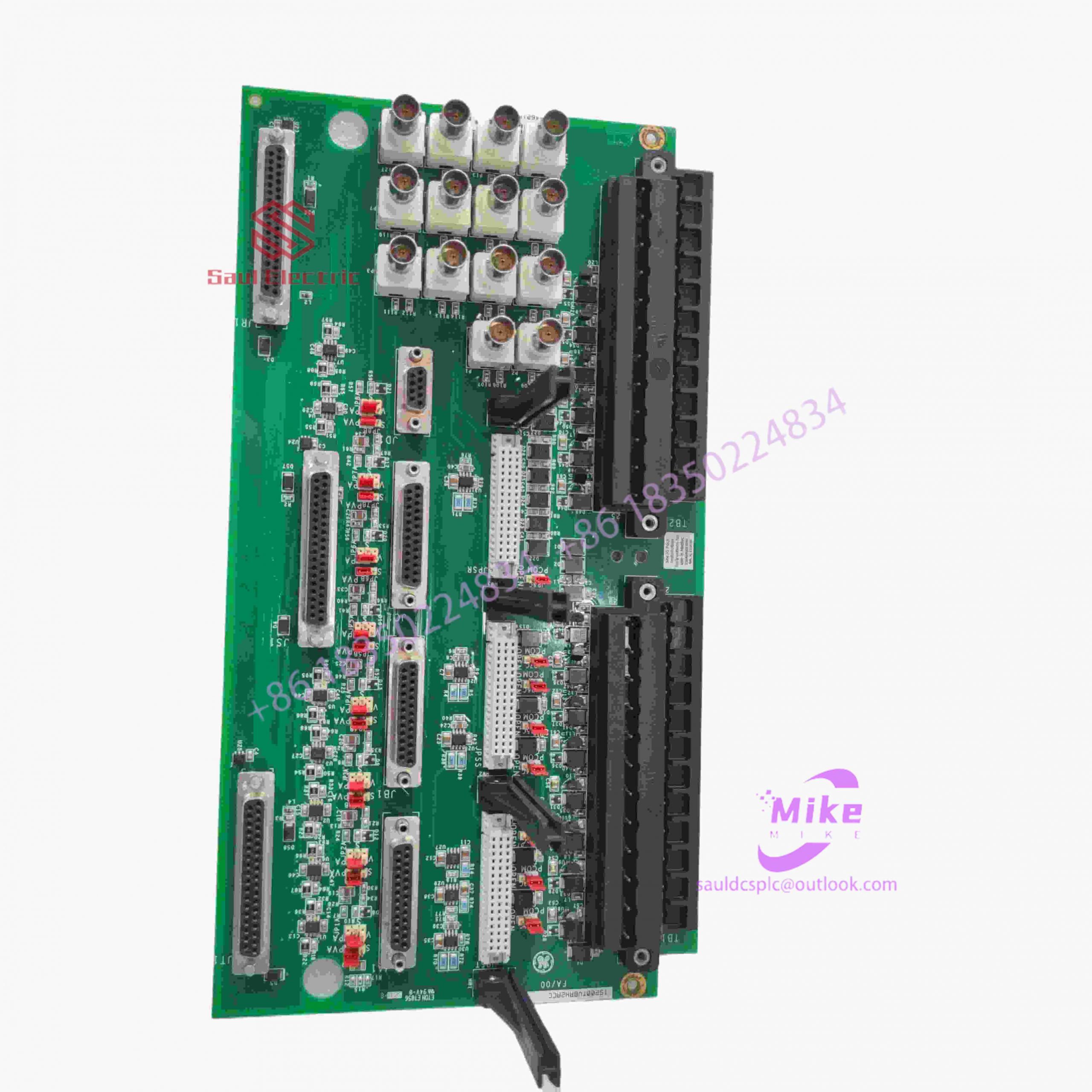
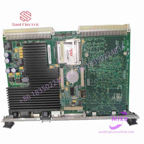
DS200DENCF1ACH Product Introduction
Basic Information
Brand: GE (General Electric)
Model:DS200DENCF1ACH
Part Number: DS200DENCF1ACH
Series: Mark VIe Speedtronic Turbine Control System I/O Pack
Country of Origin: United States
Product Type: Discrete Input Module (Contact Input Module), also known as PDIA I/O Pack
 Functional Overview
The DS200DENCF1ACH is a 24-channel discrete (digital) input module in the GE Mark VIe control system. Its primary function is to collect discrete signals (contact open/close signals) generated by field devices such as sensors,
switches, and relays, convert them into digital signals that can be recognized and processed by the PLC or control system CPU,
and transmit the processed data to the GE Speedtronic turbine control system or other control equipment, enabling automated control and monitoring. Key Technical Specifications
Rated Voltage: 24.0 VDC (Nominal)
Maximum Rated Voltage: 28.6 VDC
Maximum Rated Contact Input Voltage: 32 VDC
Number of Input Channels: 24 Discrete Inputs
Operating Temperature Range: -30°C to +65°C
Environmental Adaptability: Passes rigorous environmental testing, capable of long-term stable operation in harsh industrial environments Compatible Terminal Boards
The DS200DENCF1ACH can be paired with a variety of GE terminal boards, including but not limited to:
IS200STCIH1A / IS200STCIH2A
IS200STCIH8A
IS200TBCIH2C / IS200TBCIH4C
IS400STCIH1A / IS400STCIH2A / IS400STCIH8A
IS400TBCIH2C Certifications and Safety
This module is UL certified and can be used in both hazardous and non-hazardous locations. The UL certification covers various classes and divisions, and relevant UL mark documents are available for reference.
user experience
Secondly, if power system engineers are to consider the convenience and speed of using the product in the future, operability needs to be improved while ensuring stability. This requires a simple self-service system and an operation interface with good visual effects that can meet the needs of users. Some operating habits and other aspects
* cut costs
Furthermore, since there are many nodes in the power system, the same product needs to be deployed on many nodes. Then when the quantity of required products increases, cost issues will inevitably be involved. How to solve the research and development, construction and installation of products and better reduce operating expenses is also a major issue that ABB needs to consider.
Implementation of communication between Omron vision system and ABB industrial robot
introduction
In modern production processes, vision systems are often used to measure and identify products, and then the results are transmitted to industrial robots for work through communications . In this process, communication settings are very important. This article analyzes the communication implementation process between the Omron FH-L550 vision system and ABB industrial robots. The main task is to enable the vision system to provide data detection results for ABB industrial robots, and the industrial robots perform related operations based on the data results. This article mainly discusses the entire process of visual system communication transmission implementation.
1Ethernet-based communication settings in vision software
The main communication methods of Omron FH-L550 vision system controller are as follows [2], namely: parallel communication, PLCLINK communication, Ethernet communication, EtherCAT communication, and protocol-free communication. These five communication methods have their own characteristics in the communication process. In modern equipment, Ethernet communication (Ethernet communication) is the most common, so this article uses the Ethernet communication method as an example to analyze and explain.
First, select the “Tools” option in the main interface, select the “System Settings” menu (Figure 1), after entering the “System Settings” menu, click the “Startup Settings” option, and select the “Communication Module” tab (Figure 2 ), after completing the above settings, return to the main interface to save the settings (Figure 3). Finally, select the function menu to perform system restart settings, and wait for the system to complete the restart before proceeding to the next step.
After the system restarts, click the “System Settings” menu again and select the “Ethernet (No Protocol (UDP))” option (Figure 4). In this option, there will be parameter settings such as IP address and port. What needs to be noted here are the two IP address parameters. The parameters in “Address Setting 2” need to be filled in. The information that needs to be filled in includes the IP address of the vision controller, subnet mask, default gateway and DNS server.
In the port number setting of “Input/Output Settings” at the bottom of the menu, set the port number for data input with the sensor controller. Note that the port number should be the same as the host side, and finally complete the settings and corresponding data saving work.
2ABB industrial robot communication settings
First, configure the WAN port IP address for the ABB industrial robot. Select the control panel in the teach pendant, then select configuration, then select communication in the theme, click IPSetting, set the IP information and click “Change” to save the IP information.
Next, use the SocketCreate robot command to create a new socket using the streaming protocol TCP/IP and assign it to the corresponding variable (Figure 5). Then use the SocketConnect command to connect the socket to the remote computer. After the communication connection is completed, it is necessary to send and receive information from the visual system. To send information, use the SocketSend instruction to send data instructions to the remote computer. After the vision system collects information and makes judgments, the industrial robot system will receive data from the remote computer. The data reception is completed using the SocketReceive instruction. This instruction stores the data in the corresponding string variable while receiving the data. Useful information needs to be extracted from the received data information, which requires StrPart to find the specified character position instruction, extract the data at the specified position from the string, and assign the result to a new string variable. Finally, when the socket connection is not in use, use SocketCloSe to close it.

There are no reviews yet.