
 HONG KONG SAUL
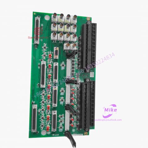
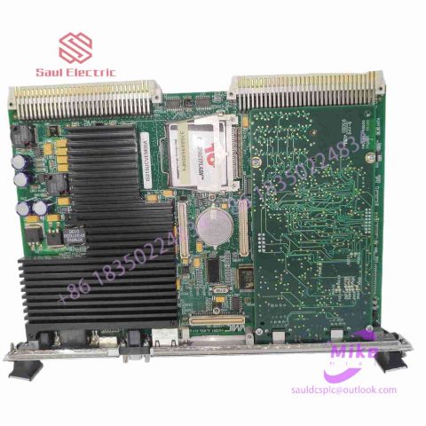
DS200DMCBF1CIA Mark VIe Control System
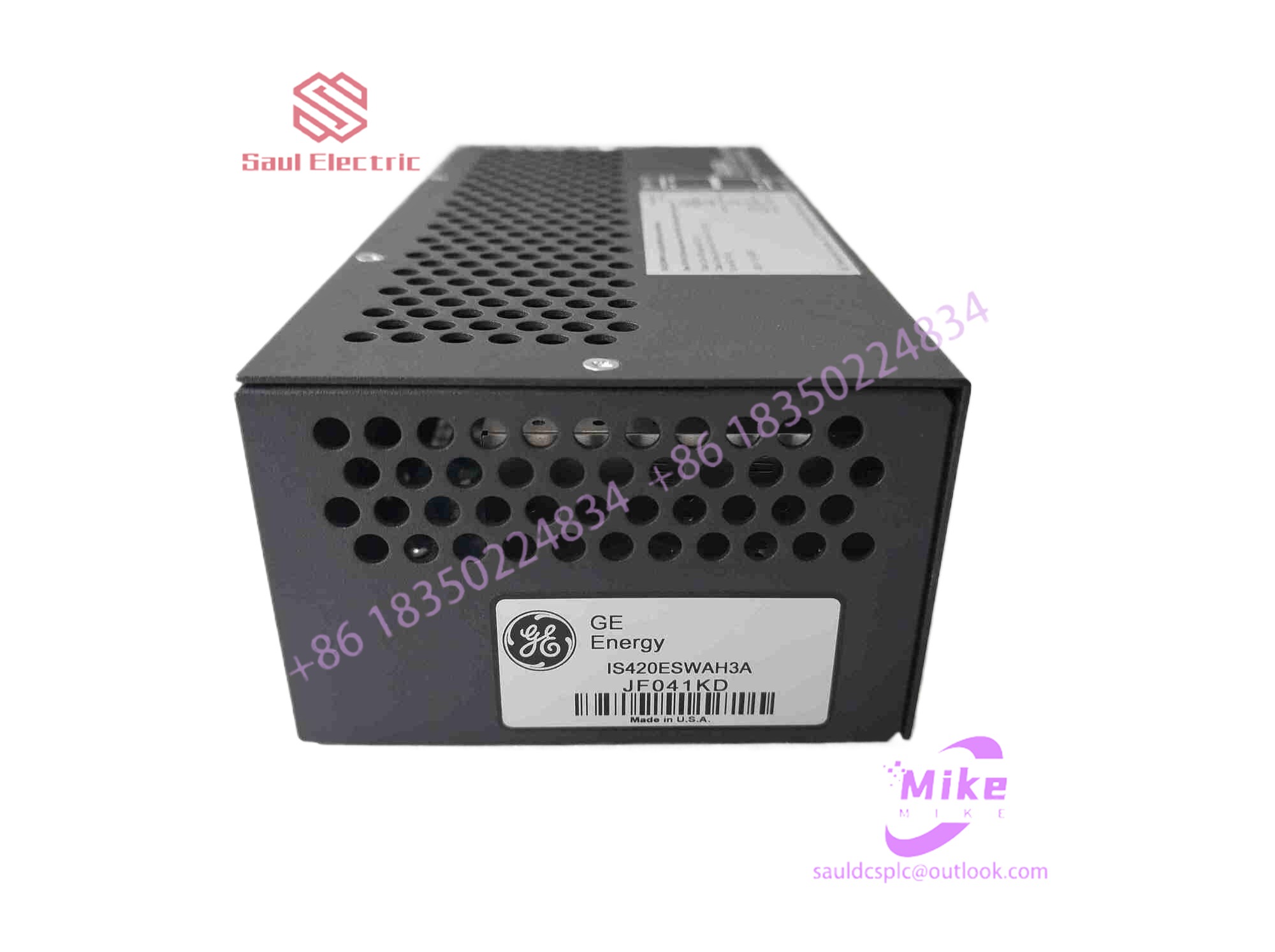
DS200DMCBF1CIA Product Introduction
Basic Information
Brand: GE (General Electric)
Model:DS200DMCBF1CIA
Part Number: DS200DMCBF1CIA
Series: Mark VIe Speedtronic Turbine Control System I/O Pack
Country of Origin: United States
Product Type: Discrete Input Module (Contact Input Module), also known as PDIA I/O Pack
 Functional Overview
The DS200DMCBF1CIA is a 24-channel discrete (digital) input module in the GE Mark VIe control system. Its primary function is to collect discrete signals (contact open/close signals) generated by field devices such as sensors,
switches, and relays, convert them into digital signals that can be recognized and processed by the PLC or control system CPU,
and transmit the processed data to the GE Speedtronic turbine control system or other control equipment, enabling automated control and monitoring. Key Technical Specifications
Rated Voltage: 24.0 VDC (Nominal)
Maximum Rated Voltage: 28.6 VDC
Maximum Rated Contact Input Voltage: 32 VDC
Number of Input Channels: 24 Discrete Inputs
Operating Temperature Range: -30°C to +65°C
Environmental Adaptability: Passes rigorous environmental testing, capable of long-term stable operation in harsh industrial environments Compatible Terminal Boards
The DS200DMCBF1CIA can be paired with a variety of GE terminal boards, including but not limited to:
IS200STCIH1A / IS200STCIH2A
IS200STCIH8A
IS200TBCIH2C / IS200TBCIH4C
IS400STCIH1A / IS400STCIH2A / IS400STCIH8A
IS400TBCIH2C Certifications and Safety
This module is UL certified and can be used in both hazardous and non-hazardous locations. The UL certification covers various classes and divisions, and relevant UL mark documents are available for reference.
When a finger touches the screen, the two conductive layers that are usually insulated from each other come into contact at the touch point. Because one of the conductive layers is connected to a 5V uniform voltage field in the Y-axis direction, the voltage of the detection layer changes from zero to Non-zero, after the controller detects this connection, it performs A/D conversion and compares the obtained voltage value with 5V to obtain the Y-axis coordinate of the touch point. In the same way, the X-axis coordinate is obtained. This is The most basic principle common to all resistive technology touch screens.
The key to resistive touch screens lies in material technology. Commonly used transparent conductive coating materials are:
①ITO, indium oxide, weak conductor, the characteristic is that when the thickness drops below 1800 angstroms (angstroms = 10-10 meters), it will suddenly become transparent, with a light transmittance of 80%. The transmittance decreases as it gets thinner, and rises to 80% when the thickness reaches 300 angstroms. ITO is the main material used in all resistive technology touch screens and capacitive technology touch screens. In fact, the working surface of resistive and capacitive technology touch screens is the ITO coating.
② Nickel-gold coating, the outer conductive layer of the five-wire resistive touch screen uses a nickel-gold coating material with good ductility. Due to frequent touching, the purpose of using a nickel-gold material with good ductility for the outer conductive layer is to extend the service life. However, the process cost is relatively high. Although the nickel-gold conductive layer has good ductility, it can only be used as a transparent conductor and is not suitable as a working surface for a resistive touch screen. Because it has high conductivity and the metal is not easy to achieve a very uniform thickness, it is not suitable for use as a voltage distribution layer and can only be used as a detector. layer.
Five-wire resistive touch screen:
The base layer of the five-wire resistive technology touch screen adds voltage fields in both directions to the conductive working surface of the glass through a precision resistor network. We can simply understand that the voltage fields in both directions are added to the conductive working surface in a time-sharing manner. On the same working surface, the outer nickel-gold conductive layer is only used as a pure conductor. There is a method of timely detecting the X-axis and Y-axis voltage values of the inner ITO contact point after touching to measure the position of the touch point. The five-wire resistive touch screen requires four leads in the inner layer of ITO, and only one conductor in the outer layer. The touch screen has a total of 5 leads. The structure of the five-wire resistive touch screen is shown in Figure 6-5
Figure 6-5 Structure of five-wire touch screen
Disadvantages of the four-wire resistive touch screen:
The B side of the resistive touch screen needs to be touched frequently. The B side of the four-wire resistive touch screen uses ITO. We know that ITO is an extremely thin oxidized metal. During use, small particles will soon form. Once a crack occurs, the current flowing there is forced to go around the crack, and the voltage that should be evenly distributed is destroyed, and the touch screen is damaged, which is manifested as inaccurate crack placement.
Figure 6-6 Cracks in the four-wire touch screen lead to shunting
As the cracks intensify and increase, the touch screen will gradually fail. Therefore, the short service life is the main problem of the four-wire resistive touch screen.
Improvements of the five-wire resistive touch screen:
First, the A side of the five-wire resistive touch screen is conductive glass instead of a conductive coating. The conductive glass process greatly improves the life of the A side and can increase the light transmittance.
Secondly, the five-wire resistive touch screen assigns all the tasks of the working surface to the long-life A side, while the B side is only used as a conductor, and uses a nickel-gold transparent conductive layer with good ductility and low resistivity. Therefore, the B side Life span is also greatly improved.
Another proprietary technology of the five-wire resistive touch screen is to use a precision resistor network to correct the linearity problem on the A side: due to the inevitable uneven thickness of the process engineering, which may cause uneven distribution of the voltage field, the precision resistor network flows during operation. It passes most of the current, so it can compensate for the possible linear distortion of the working surface.
The five-wire resistive touch screen is currently the best resistive technology touch screen and is most suitable for use in the military and medical fields.
However, the four-wire resistive touch screen is used in general fields due to its low price. The following will explain in detail the work and measurement process of the entire touch screen circuit in conjunction with the built-in touch screen controller of S3C2410 .
The following figure is the equivalent circuit when measuring a four-wire resistive touch screen (Figure 6-7):

There are no reviews yet.