
 HONG KONG SAUL

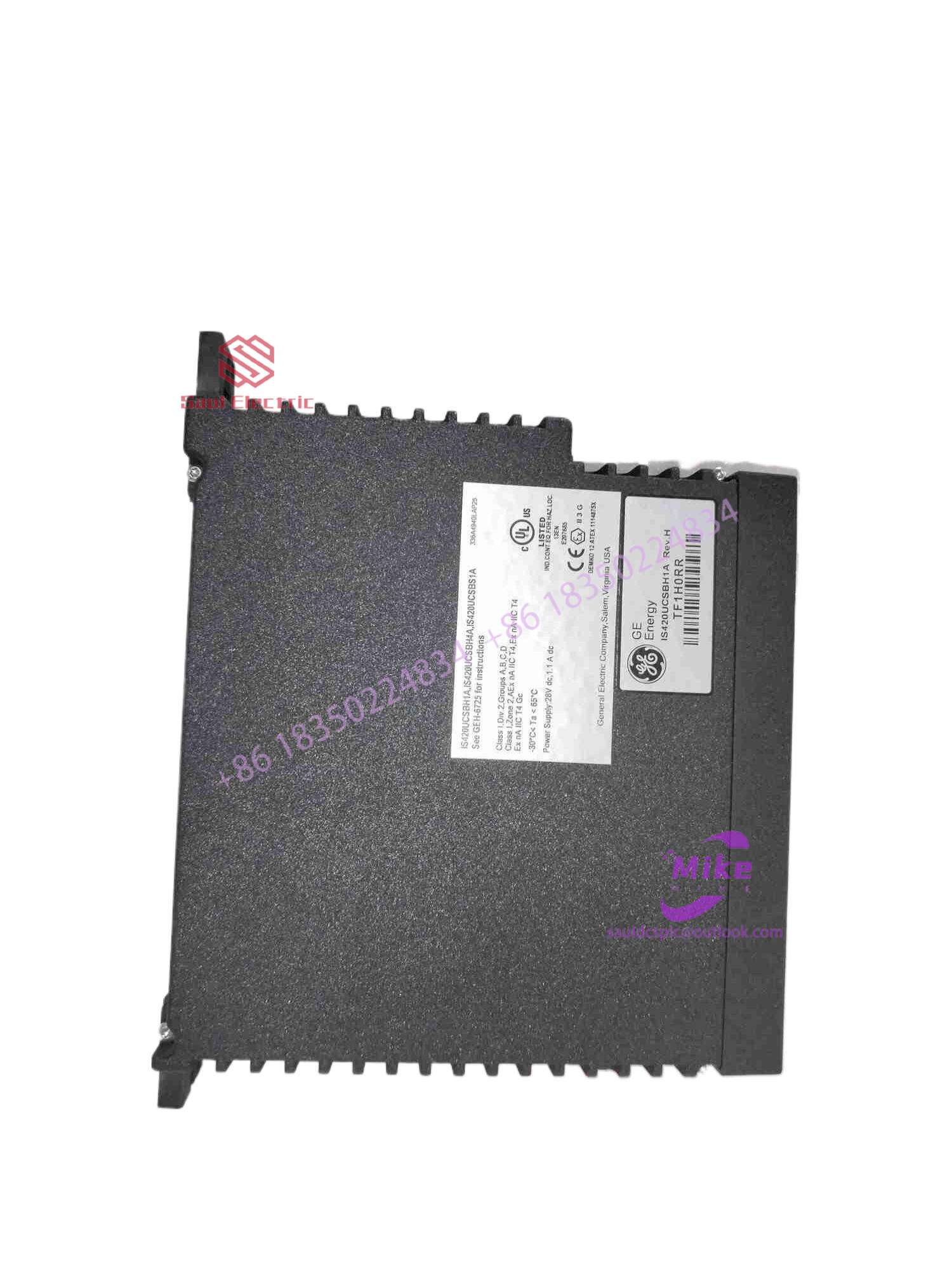
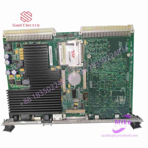
DS200FEOBG1AAA Mark VIe Control System
DS200FEOBG1AAA Product Introduction
Basic Information
Brand: GE (General Electric)
Model:DS200FEOBG1AAA
Part Number: DS200FEOBG1AAA
Series: Mark VIe Speedtronic Turbine Control System I/O Pack
Country of Origin: United States
Product Type: Discrete Input Module (Contact Input Module), also known as PDIA I/O Pack
contacts: Mike
+86 18350224834 (WeChat/WhatsApp)
Email:Mike18350224834@gmail.com
 Functional Overview
The DS200FEOBG1AAA is a 24-channel discrete (digital) input module in the GE Mark VIe control system. Its primary function is to collect discrete signals (contact open/close signals) generated by field devices such as sensors,
switches, and relays, convert them into digital signals that can be recognized and processed by the PLC or control system CPU,
and transmit the processed data to the GE Speedtronic turbine control system or other control equipment, enabling automated control and monitoring. Key Technical Specifications
Rated Voltage: 24.0 VDC (Nominal)
Maximum Rated Voltage: 28.6 VDC
Maximum Rated Contact Input Voltage: 32 VDC
Number of Input Channels: 24 Discrete Inputs
Operating Temperature Range: -30°C to +65°C
Environmental Adaptability: Passes rigorous environmental testing, capable of long-term stable operation in harsh industrial environments Compatible Terminal Boards
The DS200FEOBG1AAA can be paired with a variety of GE terminal boards, including but not limited to:
IS200STCIH1A / IS200STCIH2A
IS200STCIH8A
IS200TBCIH2C / IS200TBCIH4C
IS400STCIH1A / IS400STCIH2A / IS400STCIH8A
IS400TBCIH2C Certifications and Safety
This module is UL certified and can be used in both hazardous and non-hazardous locations. The UL certification covers various classes and divisions, and relevant UL mark documents are available for reference.
Implementation of communication between ABC industrial robot and PLC based on DeviceNet fieldbus technology
introduction
In modern production systems, industrial robots and PLCs need to communicate and collaborate to complete production tasks. That is, the industrial robots output signals to the PLC, allowing the PLC to control related equipment to drive the robot’s front-end tools. This article mainly analyzes the communication problems between ABB industrial robots and PLC based on DeviceNet fieldbus technology. DeviceNet is a common network communication method in the field of automation. ABB industrial robots establish a network to communicate with Siemens PLC based on the DeviceNet network.
1Configure DSQC652
There are mainly 5 types of standard I/0 boards commonly used in ABB industrial robots [2]. Except for the different addresses assigned to them during setup, their configuration methods are basically the same. This article mainly analyzes the ABB standard I/0 board DS0C652, which mainly builds communication modules based on the DeviceNet network. The DS0C652 board has a distributed I/O module with 16 digital input and 16 digital output interfaces. The board is installed in the ABB industrial robot control cabinet. First, define the specific operation steps of the DS0C652 board, enter the teach pendant control panel, then enter the configuration menu (Figure 1), select the DeviceNetDevice menu, and add a template to enter Figure 2. ABB standard I/0 board is hung on the DeviceNet network, so the address of the module in the network must be set. The jumpers 6 to 12 of terminal x5 are used to determine the address of the module. The available address range is 10 to 63. Modify the parameters in the template parameters to complete the DS0C652 board settings. Click the drop-down menu to select the “Use value from template” row, select “DS0C65224VDCI/0Device”, and then the parameters that need to be set include the address of the I/0 board in the bus.
Figure 1 Configuring DSQC652
2Configure signals and parameters
After completing the DS0C652 board setting, the I/0 signal setting will be performed. Setting the I/0 signal is the basis for establishing communication with the PLC. The PLC communicates and transmits data with the ABB industrial robot through the I/0 signal and the DS0C652 board. As shown in Figure 3, in the signal configuration interface, there are many default I/0 points after the system is established. Modification is not allowed. Click “Add” to add signals. When setting input and output signals, their address range is 0~15. First, enter the signal menu in the configuration options to set the input and output types, and modify the corresponding parameters. After completing the settings, the computer prompts that you need to restart the settings. If there are multiple signals that need to be defined and the waiting time is long after restarting multiple times, you can click “Cancel” and wait for all signals to be defined before clicking the “Yes” button to restart. After the signal settings are completed, click to select “Input and Output” in the ABB menu to check whether all signals have been set.
Figure 2 Configure DSQC652 parameters
Figure 3 Signal parameter settings
During the signal establishment process, attention should be paid to the DSoC652 port and PLC port addresses used, and the corresponding address table should be established, as shown in Table 1. The robot interacts with the PLC through I/O signals. During the setting process, there must be no errors in the port and address number of the PLC connected to the DSoC652. If the address is set incorrectly, the communication between the robot and the PLC will not work properly.
The entire robot teaching pendant setting process is shown in Figure 4.

There are no reviews yet.