
 HONG KONG SAUL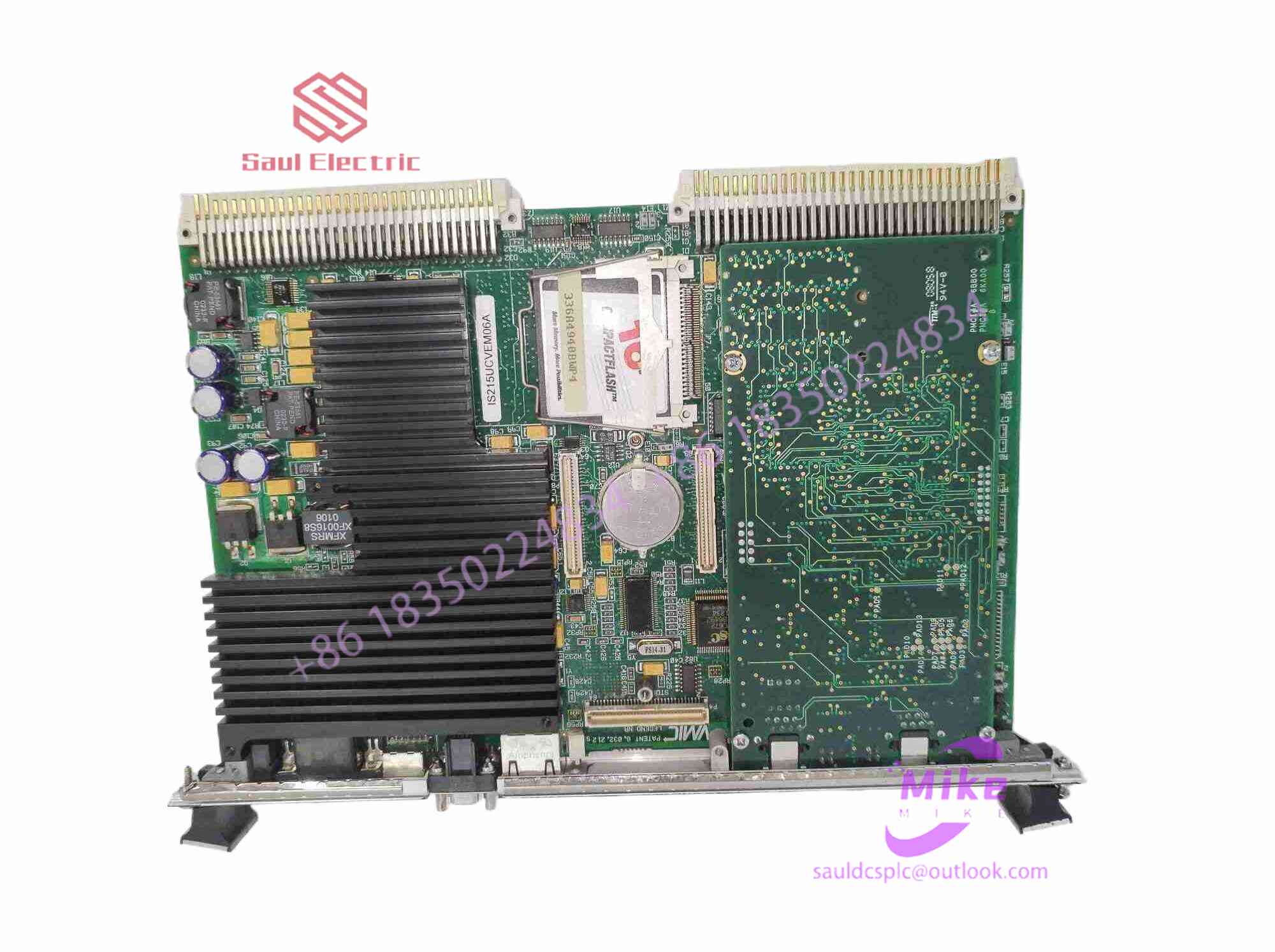

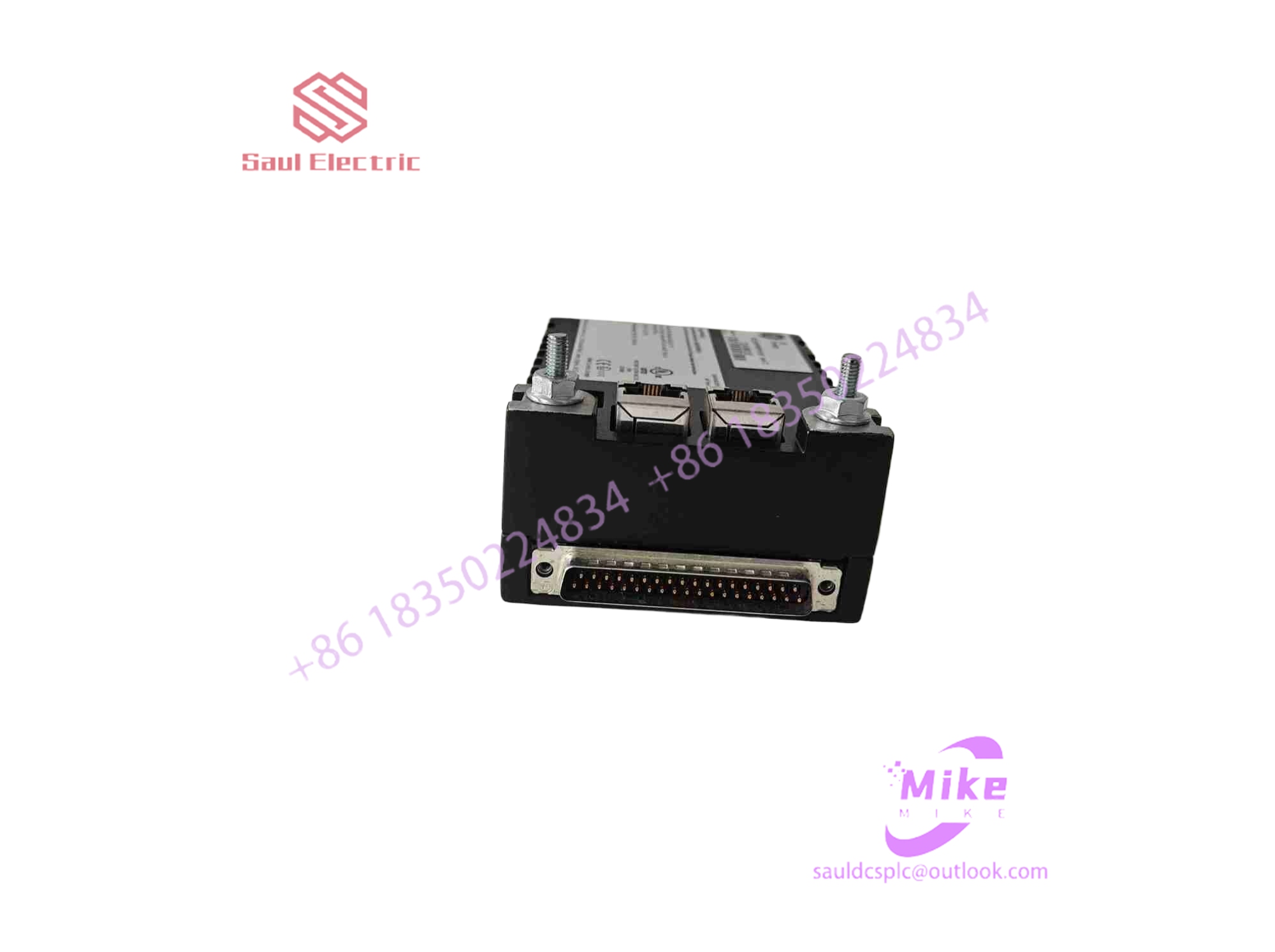
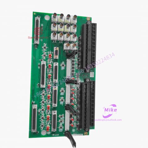
DS200GASCF1BGB Mark VIe Control System
DS200GASCF1BGB Product Introduction
Basic Information
Brand: GE (General Electric)
Model:DS200GASCF1BGB
Part Number: DS200GASCF1BGB
Series: Mark VIe Speedtronic Turbine Control System I/O Pack
Country of Origin: United States
Product Type: Discrete Input Module (Contact Input Module), also known as PDIA I/O Pack
contacts: Mike
+86 18350224834 (WeChat/WhatsApp)
Email:Mike18350224834@gmail.com
 Functional Overview
The DS200GASCF1BGB is a 24-channel discrete (digital) input module in the GE Mark VIe control system. Its primary function is to collect discrete signals (contact open/close signals) generated by field devices such as sensors,
switches, and relays, convert them into digital signals that can be recognized and processed by the PLC or control system CPU,
and transmit the processed data to the GE Speedtronic turbine control system or other control equipment, enabling automated control and monitoring. Key Technical Specifications
Rated Voltage: 24.0 VDC (Nominal)
Maximum Rated Voltage: 28.6 VDC
Maximum Rated Contact Input Voltage: 32 VDC
Number of Input Channels: 24 Discrete Inputs
Operating Temperature Range: -30°C to +65°C
Environmental Adaptability: Passes rigorous environmental testing, capable of long-term stable operation in harsh industrial environments Compatible Terminal Boards
The DS200GASCF1BGB can be paired with a variety of GE terminal boards, including but not limited to:
IS200STCIH1A / IS200STCIH2A
IS200STCIH8A
IS200TBCIH2C / IS200TBCIH4C
IS400STCIH1A / IS400STCIH2A / IS400STCIH8A
IS400TBCIH2C Certifications and Safety
This module is UL certified and can be used in both hazardous and non-hazardous locations. The UL certification covers various classes and divisions, and relevant UL mark documents are available for reference.
What types of resistive touch screens are there and what is their structure?
The touch screens we commonly use today can be divided into four categories: resistive touch screens, surface capacitive touch screens, infrared touch screens, and surface acoustic wave touch screens.
1. Resistive touch screen: The structure of the resistive touch screen is to form a transparent conductive film on a glass substrate, set a spacer on it, and then set a transparent conductive film. An electric field is applied in the vertical direction on the upper conductive film and the lower glass substrate respectively. When a finger or other object touches any position of the upper conductive film, that part will be energized with the conductive film on the lower glass substrate, and the touched position is calculated by measuring the voltage drop at this time.
2. Capacitive touch screen: The capacitive touch screen is plated with long and narrow electrodes on all four sides of the touch screen. The voltage is connected to the four corners, forming a low-voltage AC electric field in the conductive body. When a finger touches the screen surface, a coupling capacitance is formed between the finger and the conductor. The current emitted by the electrodes on the four sides flows to the touch point. Because the working surface is connected to a high-frequency signal, the finger will absorb a very small current. This current flows out from the electrodes on the four corners of the touch screen respectively. The strength of the current depends on the distance between the finger and the electrode. Proportional to the distance, the location of the touch point can be calculated.
3. Infrared touch screen: Infrared touch screen has infrared transmitting tubes and receiving tubes arranged on the four sides of the screen frame, which correspond to each other to form a horizontal and vertical infrared matrix. When we touch a certain point on the screen with our fingers, it will block the infrared light passing through that position. There are two horizontal and vertical infrared rays, and the central processor uses this to calculate the position of the touch point. It is mainly composed of infrared transmitting and receiving sensing elements installed on the outer frame of the touch screen.
4. Surface acoustic wave touch screen: Surface acoustic wave touch screen is a sound wave generator, reflector and sound wave receiver installed on the surface of the display. The sound wave generator sends a high-frequency sound wave across the screen surface. When the finger touches the screen, the contact point The sound waves are blocked and the central processor determines the location of the touch point.
Introduction and summary of resistive touch screen types
1. Working principle of resistive touch screen:
A resistive touch screen is a sensor that converts the physical position of a touch point (X,Y) in a rectangular area into a voltage representing the X coordinate and Y coordinate. Many LCD modules use resistive touch screens, which can use four, five, seven or eight wires to generate screen bias voltage and read back the voltage of the touch point. The resistive touch screen is basically a film plus glass structure. The adjacent sides of the film and glass are coated with
ITO (Nano Indium Tin Metal Oxide) coating, ITO has good conductivity and transparency. When a touch operation is performed, the ITO on the lower layer of the film will contact the ITO on the upper layer of the glass, and the corresponding electrical signal is transmitted through the sensor, sent to the processor through the conversion circuit, and converted into X and Y values on the screen through calculation, and the point is completed. The selected action is displayed on the screen.
2. Types of resistive touch screens:
Basic structure and driving principle of resistive touch screen.pdf
Road navigation 3. The basic structure of various types of resistive touch screens: 1. Four-wire resistive touch screen
The structure of the four-wire resistive touch screen is as shown above. The glass or acrylic substrate is covered with two layers of turbine, uniformly conductive ITO layers, which are used as X electrodes and Y electrodes respectively. They are separated and insulated by evenly arranged transparent grids. . The lower ITO
Four-wire touch screen Five-wire touch screen Six-wire touch screen Seven-wire touch screen Eight-wire touch screen
It is attached to the glass substrate, and the upper ITO is attached to the PET film. The positive and negative ends of the X electrode and Y electrode are led from both ends by “conductive strips” (black strips in the figure), and the positions of the X electrode and Y electrode conductive strips are perpendicular to each other. There are four wires in total at the lead-out terminals: X-, X+, Y-, and Y+. This is where the name of the four-wire resistive touch screen comes from. When an object touches the touch screen surface and exerts a certain amount of pressure, the upper IT
The O conductive layer deforms and comes into contact with the underlying ITO. This structure can be equivalent to the corresponding circuit, as shown below
2. Eight-wire resistive touch screen
How about Samsung i8262d? The structure of the eight-wire resistive touch screen is similar to that of the four-wire one. The difference is that in addition to the four electrodes of X-drive, X- sense, X+ sense, Y- sense, Y+ sense, so there ar

There are no reviews yet.