
 HONG KONG SAUL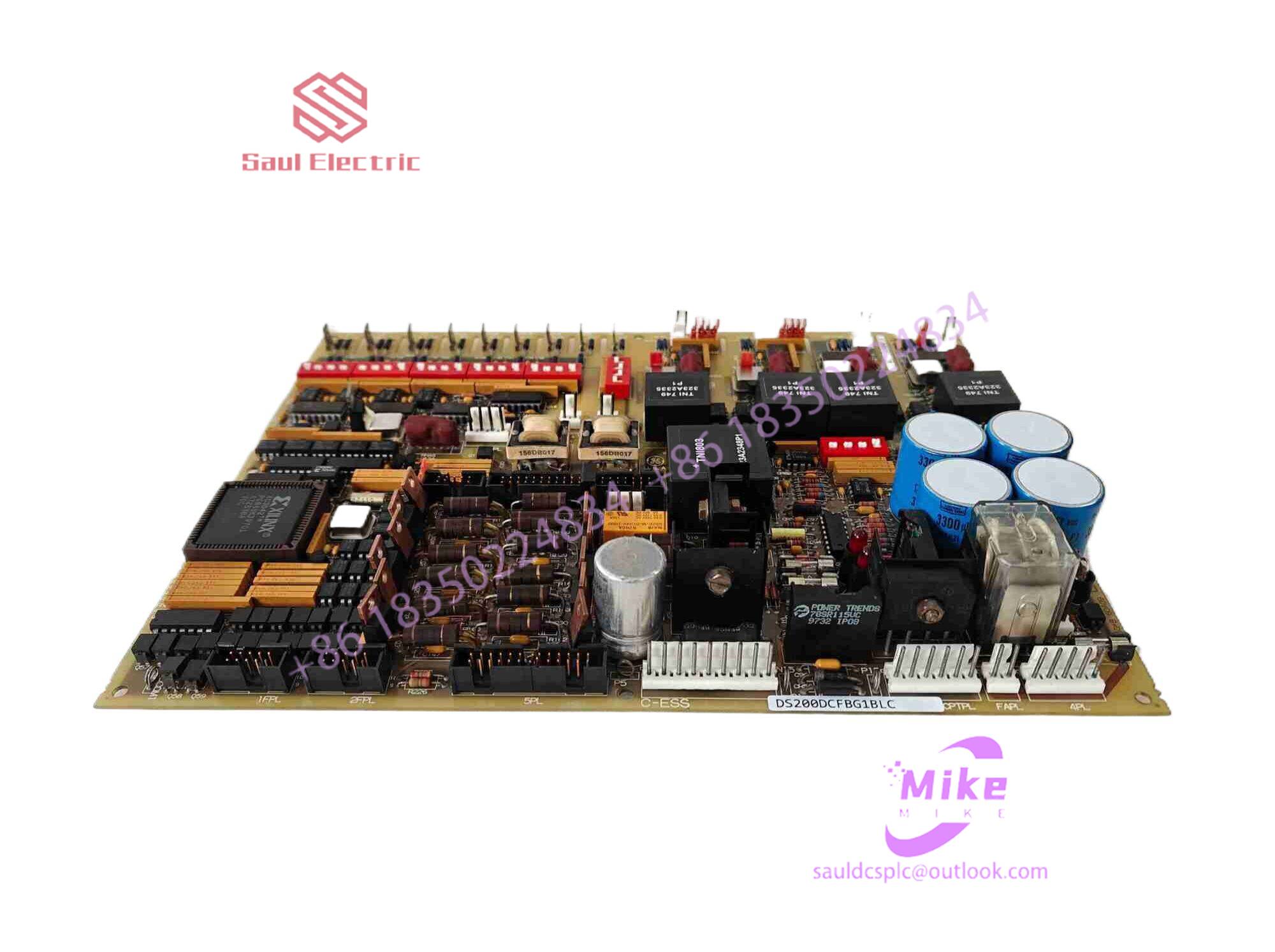

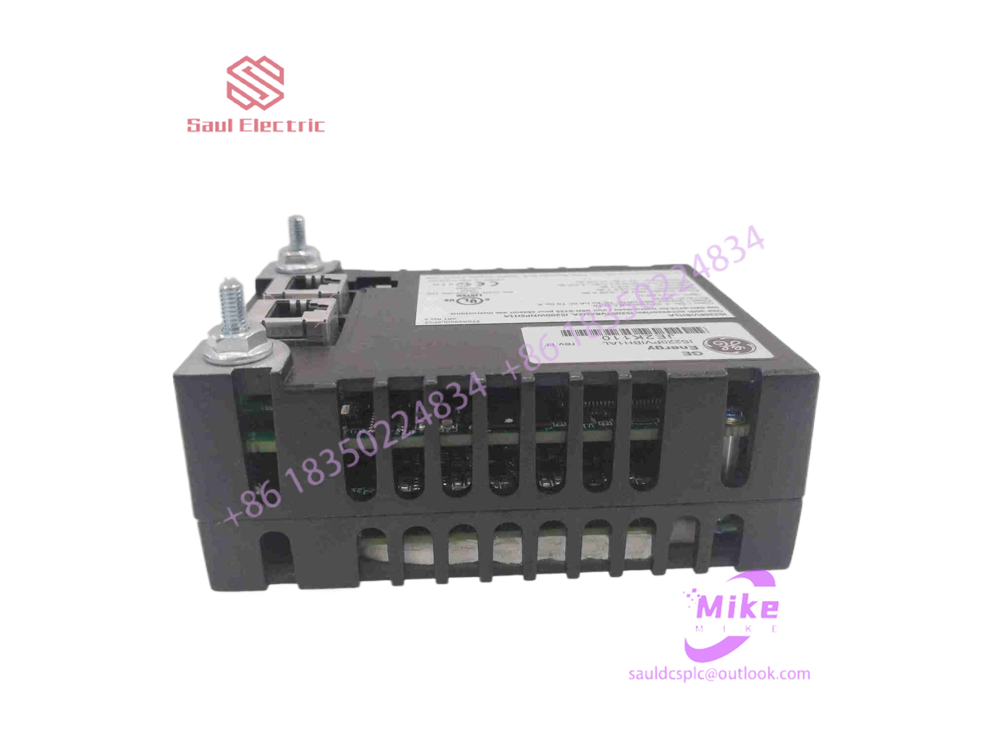
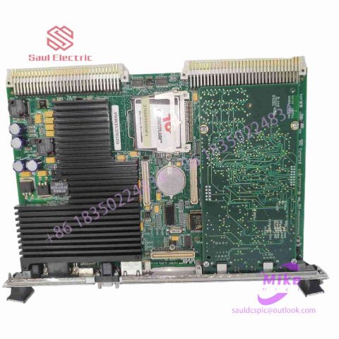
DS200RCTBG1ABA integrated circuit board
DS200RCTBG1ABA Product Introduction
Basic Information
Brand: GE (General Electric)
Model:DS200RCTBG1ABA
Part Number: DS200RCTBG1ABA
Series: Mark VIe Speedtronic Turbine Control System I/O Pack
Country of Origin: United States
Product Type: Discrete Input Module (Contact Input Module), also known as PDIA I/O Pack
contacts: Mike
+86 18350224834 (WeChat/WhatsApp)
Email:Mike18350224834@gmail.com
 Functional Overview
The DS200RCTBG1ABA is a 24-channel discrete (digital) input module in the GE Mark VIe control system. Its primary function is to collect discrete signals (contact open/close signals) generated by field devices such as sensors,
switches, and relays, convert them into digital signals that can be recognized and processed by the PLC or control system CPU,
and transmit the processed data to the GE Speedtronic turbine control system or other control equipment, enabling automated control and monitoring. Key Technical Specifications
Rated Voltage: 24.0 VDC (Nominal)
Maximum Rated Voltage: 28.6 VDC
Maximum Rated Contact Input Voltage: 32 VDC
Number of Input Channels: 24 Discrete Inputs
Operating Temperature Range: -30°C to +65°C
Environmental Adaptability: Passes rigorous environmental testing, capable of long-term stable operation in harsh industrial environments Compatible Terminal Boards
The DS200RCTBG1ABA can be paired with a variety of GE terminal boards, including but not limited to:
IS200STCIH1A / IS200STCIH2A
IS200STCIH8A
IS200TBCIH2C / IS200TBCIH4C
IS400STCIH1A / IS400STCIH2A / IS400STCIH8A
IS400TBCIH2C Certifications and Safety
This module is UL certified and can be used in both hazardous and non-hazardous locations. The UL certification covers various classes and divisions, and relevant UL mark documents are available for reference.
Figure 4 Tool Framework
2.3Smart component creation
Call the Rotator component: This component is used to allow the rotatable grinding rotor to rotate during simulation to simulate the real grinding scene. In the parameters of the Rotator component, set the reference to object, the reference object to the frame l, and the object to a copy of the rotor. (2) The rotary grinding rotor can be rotated, and the speed is l20mm/s (the speed of the grinding head will affect the quality of the finished product) ), the reference center axis is: axis (based on frame l, centerpoint x, y,: set to 0, 0, 0, Axis set x, y,: 0, 0, l000mm).
Call the Attach component: This component is used to allow the rotatable grinding rotor to be integrated with the tool body. When the tool body is installed on the flange, it can follow the movement of the flange. In the parameters of the Attach component, set the sub-object to be a copy of the rotor (2) for the rotatable polishing rotor, and the parent object is the tool body of a copy of the rotor. The offset and orientation are based on the offset of point B relative to the origin. For setting, you can use the measurement tool in Robotstudio software to measure, and then set the parameters after measurement.
Verification: Install a copy of the rotor tool body onto the robot flange, and then click Execute in the Attach component. You can observe whether the position of the rotatable grinding rotor is correct at this time. If there is a deviation, adjust the position in time, as shown in the figure. 5 shown.
Figure 5 Tool installation
2.4 Create tool coordinate system
Use the six-point method to create the tool coordinate system Too1data on the robot teach pendant at the center of the rotor. Change the tool coordinate system to Too1data in the basic options. At this time, click on the robot manual linear and you can drag the robot to move linearly at will.
2.5 Creating trajectories and programming
Determine the trajectory: According to the requirements of the work task, design the grinding trajectory around the workpiece and determine the trajectory points and transition points required for the grinding trajectory. The grinding action process is shown in Figure 6.
Setting I/O and programming: Yalong IY-l3-LA industrial robot deburring and grinding system control and application equipment adopts 0sDC-52 6/o communication board, the address is 10, Do1 is the digital output signal, the address is 1 . First set the I/O board, then set the I/O digital output signal Di1, and then program on the simulation teaching pendant. The procedure is as follows:
PRoCmain()
setDo1: Set the Do1 signal to allow the external grinding rotor to start rotating.
waitTime1: The robot stays in place and does not move, waits for 1s, and lets the polishing rotor turn to the specified speed, transition
MoveAbsjjpos10NoEoffs,v1000,z50,Too1data1: The robot moves to the initial point jpos10 above point p10. Point jpos10 is used as the starting point and end point of the robot’s action.
Move4p10,v1000,z50,Too1data1: Move straight line grinding to point p10
Move4pL0,v1000,z50,Too1data1: Move straight line grinding to pL0 point
Move4p30,v1000,z50,Too1data1: Move straight line grinding to point p30
Move4p40,v1000,z50,Too1data1: Move straight line grinding to p40 point
Move4p10,v1000,z50,Too1data1: Move straight line grinding to point p10
MoveAbsjjpos10NoEoffs,v1000,z50,Too1data1: The robot moves to the initial point jpos10 above point p10
waitTime1: wait 1s, transition
ResetDo1: Reset the Do1 signal to stop the rotor ENDPRoC
2.6 Simulation design and verification
Simulation design: Create a smart component to input the Di1 signal, and use the Di1 signal to simulate the external polishing start signal to execute the Rotator component and Attach component of the smart component to achieve the visual effect of rotating and polishing the polishing rotor. In the workstation logic design, the smart component input Di1 signal is associated with the robot Do1 signal, so that the robot signal Do1 can control the smart component input Di1 signal, thereby controlling the start and stop of the rotation of the polishing rotor.
Verification: In the program of the teaching pendant, first set the pp command to move to Main, and then set the robot startup mode to automatic. Click play in the simulation of Robotstudio software to verify whether the trajectory is consistent with the assumption, and optimize the path in time for problems existing in the simulation.
3Summary and outlook
This design is based on the programming simulation of the Yalong Y4-1360A industrial robot deburring system to control the grinding robot workstation. It covers aspects such as creating a workstation, setting up tools, creating smart components, creating tool coordinate systems, creating trajectories, programming, simulation design, and verification. Starting with it, the polishing simulation of the workstation is realized through the smart component function of Robotstudio software. The animation effect is intuitive and lifelike, which not only facilitates teaching demonstrations, but also facilitates program debugging, and has application value for both production and teaching.
In the planning and design of the workpiece grinding trajectory, according to the different roughness and grinding amount process requirements of the workpiece, the rotation speed, feed speed, feed amount, and grinding angle of the grinding rotor are also different. The feed amount can be adjusted in time according to th

There are no reviews yet.