
 HONG KONG SAUL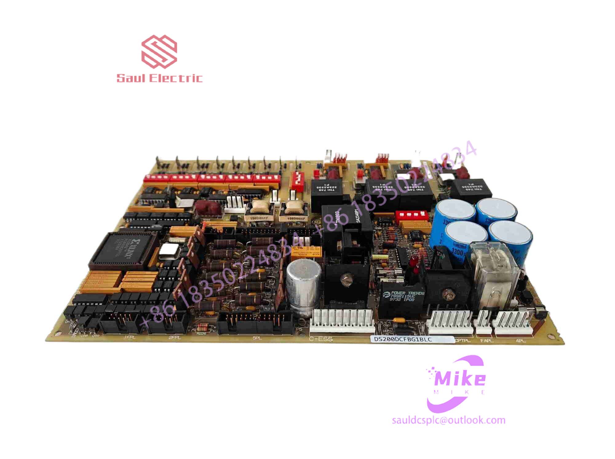

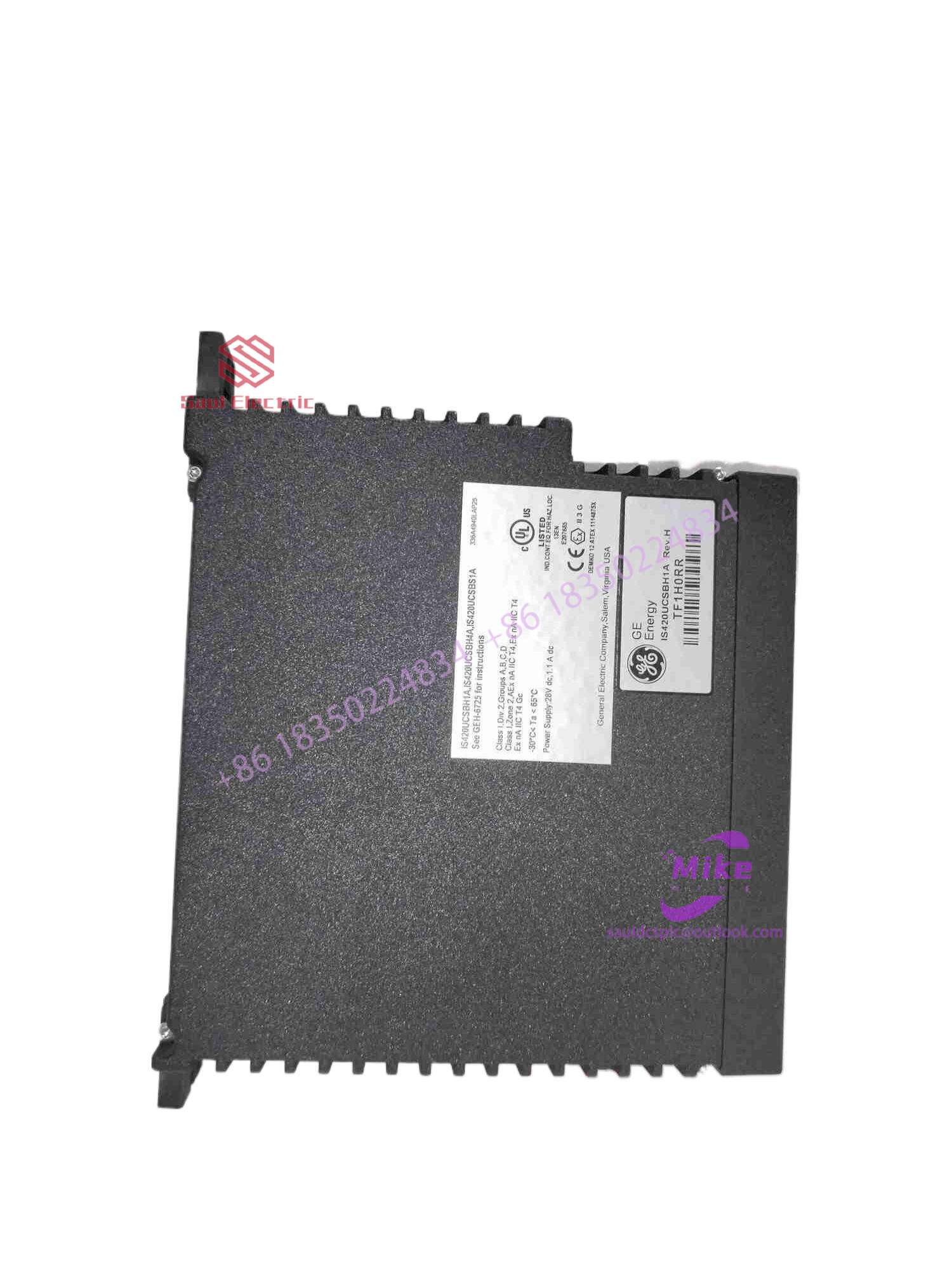
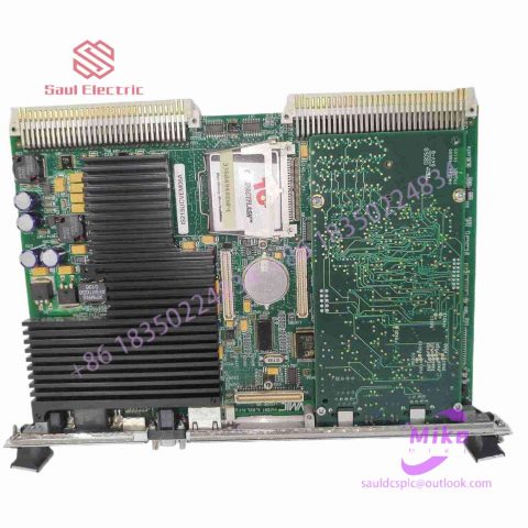
DS200TCQBF1BAE Mark VIe Control System
DS200TCQBF1BAE Product Introduction
Basic Information
Brand: GE (General Electric)
Model:DS200TCQBF1BAE
Part Number: DS200TCQBF1BAE
Series: Mark VIe Speedtronic Turbine Control System I/O Pack
Country of Origin: United States
Product Type: Discrete Input Module (Contact Input Module), also known as PDIA I/O Pack
 Functional Overview
The DS200TCQBF1BAE is a 24-channel discrete (digital) input module in the GE Mark VIe control system. Its primary function is to collect discrete signals (contact open/close signals) generated by field devices such as sensors,
switches, and relays, convert them into digital signals that can be recognized and processed by the PLC or control system CPU,
and transmit the processed data to the GE Speedtronic turbine control system or other control equipment, enabling automated control and monitoring. Key Technical Specifications
Rated Voltage: 24.0 VDC (Nominal)
Maximum Rated Voltage: 28.6 VDC
Maximum Rated Contact Input Voltage: 32 VDC
Number of Input Channels: 24 Discrete Inputs
Operating Temperature Range: -30°C to +65°C
Environmental Adaptability: Passes rigorous environmental testing, capable of long-term stable operation in harsh industrial environments Compatible Terminal Boards
The DS200TCQBF1BAE can be paired with a variety of GE terminal boards, including but not limited to:
IS200STCIH1A / IS200STCIH2A
IS200STCIH8A
IS200TBCIH2C / IS200TBCIH4C
IS400STCIH1A / IS400STCIH2A / IS400STCIH8A
IS400TBCIH2C Certifications and Safety
This module is UL certified and can be used in both hazardous and non-hazardous locations. The UL certification covers various classes and divisions, and relevant UL mark documents are available for reference.
4.2 Working principle of surface acoustic wave touch screen
Take the X-axis transmitting transducer in the lower right corner as an example: The transmitting transducer converts the electrical signal sent from the controller through the touch screen cable into sound wave energy and transmits it to the surface on the left, which is then reflected by a set of precision reflection stripes under the glass plate. The sound wave energy is reflected into an upward uniform surface and transmitted. The sound wave energy passes through the surface of the screen, and then is gathered into a line to the right by the upper reflection stripes and transmitted to the X-axis receiving transducer. The receiving transducer will return the surface acoustic wave. The energy becomes an electrical signal. When the transmitting transducer emits a narrow pulse, the sound wave energy reaches the receiving transducer through different paths. The one on the far right arrives earliest, and the one on the far left arrives last. The early and late arrivals are superimposed into one For a wider waveform signal, it is not difficult to see that the received signal collects all the sound wave energy that has returned after different long and short paths in the X-axis direction. The distance they have traveled on the Y-axis is the same, but on the The nearest one has traveled twice the maximum distance on the X-axis. Therefore, the time axis of this waveform signal reflects the position of each original waveform before superposition, which is the X-axis coordinate. When there is no touch, the waveform of the received signal is exactly the same as the reference waveform. When a finger or other object that can absorb or block sound wave energy touches the screen, the sound wave energy traveling upward along the X-axis through the finger is partially absorbed, which is reflected in the received waveform, that is, there is an attenuation gap in the waveform at a certain moment. The received waveform corresponds to the signal attenuation of a gap in the part blocked by the finger. Calculating the position of the gap means that the touch coordinate controller analyzes the attenuation of the received signal and determines the X coordinate based on the position of the gap. Then the same process for the Y axis determines the Y coordinate of the touch point. In addition to the X and Y coordinates that general touch screens can respond to, surface acoustic wave touch screens also respond to the third axis Z-axis coordinates, which means they can sense the value of the user’s touch pressure. The principle is calculated from the attenuation of the received signal attenuation. Once the three axes are determined, the controller transmits them to the host.
4.3 Characteristics of surface acoustic wave touch screen
The clarity is higher and the light transmittance is good. Highly durable and good in scratch resistance (compared to surface film on resistors, capacitors, etc.). Very responsive. Not affected by environmental factors such as temperature and humidity, high resolution and long life (50 million times with good maintenance); high light transmittance (92%), able to maintain clear and translucent image quality; no drift, only required during installation One-time correction; there is a third axis (i.e. pressure axis) response, which is currently used more in public places. Surface acoustic wave screens require regular maintenance, because dust, oil and even beverage liquids contaminating the surface of the screen will block the wave guide groove on the surface of the touch screen, preventing the waves from being emitted normally, or causing the waveform to change and the controller to be unable to recognize it normally, thus affecting the performance of the screen. For normal use of the touch screen, users must pay strict attention to environmental hygiene. The surface of the screen must be wiped frequently to keep it smooth, and a complete wipe must be performed regularly.
surface acoustic wave screen
The three corners of the sound wave screen are respectively pasted with transducers for transmitting and receiving sound waves in the X and Y directions (transducer: made of special ceramic materials, divided into transmitting transducers and receiving transducers. It controls The electrical signal sent by the device through the touch screen cable is converted into sound wave energy and the surface acoustic wave energy formed by the reflection stripes is converted into an electrical signal.), the four sides are engraved with reflection stripes that reflect surface ultrasonic waves. When a finger or soft object touches the screen, part of the sound wave energy is absorbed, thus changing the received signal. After processing by the controller, the X and Y coordinates of the touch are obtained.

There are no reviews yet.