
 HONG KONG SAUL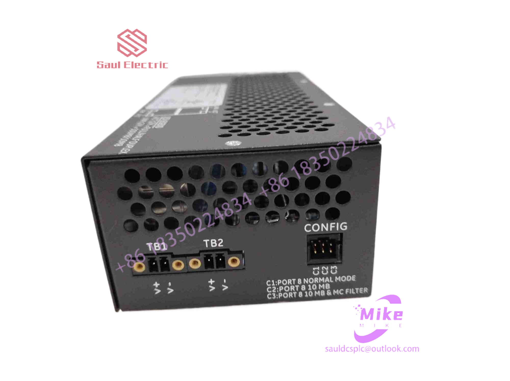

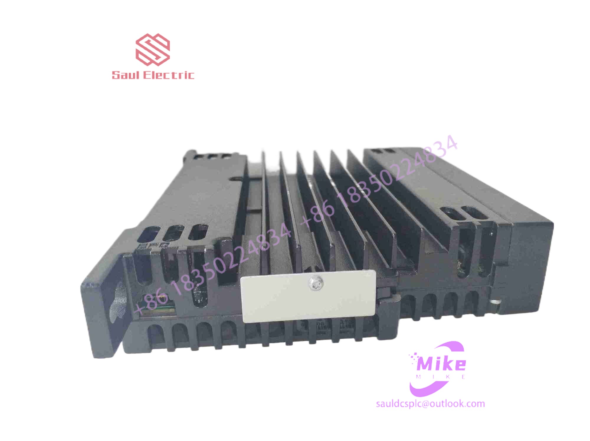
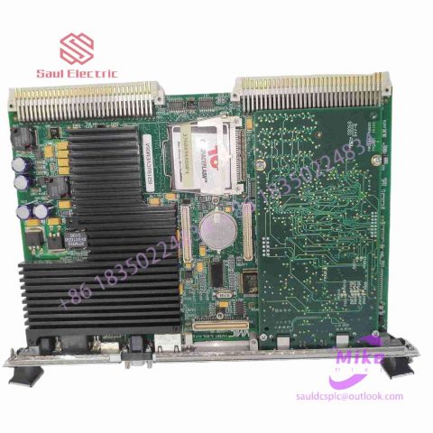
DS200TCRAG1A Mark VIe Speedtronic
DS200TCRAG1A Product Introduction
Basic Information
Brand: GE (General Electric)
Model:DS200TCRAG1A
Part Number: DS200TCRAG1A
Series: Mark VIe Speedtronic Turbine Control System I/O Pack
Country of Origin: United States
Product Type: Discrete Input Module (Contact Input Module), also known as PDIA I/O Pack
 Functional Overview
The DS200TCRAG1A is a 24-channel discrete (digital) input module in the GE Mark VIe control system. Its primary function is to collect discrete signals (contact open/close signals) generated by field devices such as sensors,
switches, and relays, convert them into digital signals that can be recognized and processed by the PLC or control system CPU,
and transmit the processed data to the GE Speedtronic turbine control system or other control equipment, enabling automated control and monitoring. Key Technical Specifications
Rated Voltage: 24.0 VDC (Nominal)
Maximum Rated Voltage: 28.6 VDC
Maximum Rated Contact Input Voltage: 32 VDC
Number of Input Channels: 24 Discrete Inputs
Operating Temperature Range: -30°C to +65°C
Environmental Adaptability: Passes rigorous environmental testing, capable of long-term stable operation in harsh industrial environments Compatible Terminal Boards
The DS200TCRAG1A can be paired with a variety of GE terminal boards, including but not limited to:
IS200STCIH1A / IS200STCIH2A
IS200STCIH8A
IS200TBCIH2C / IS200TBCIH4C
IS400STCIH1A / IS400STCIH2A / IS400STCIH8A
IS400TBCIH2C Certifications and Safety
This module is UL certified and can be used in both hazardous and non-hazardous locations. The UL certification covers various classes and divisions, and relevant UL mark documents are available for reference.
3 Basic characteristics and typical applications of ADS7846
3.1 Basic features
ADS7846 is a 4-wire touch screen controller produced by Analog Devices. It is currently widely used in resistive touch screen input systems. The ADS7846 digital converter operates in a 12-bit successive approximation comparison register (SAR) ADC architecture integrating low-pass impedance switches for driving touch screens. These devices do not use an internal reference voltage and consume less than 1.4mW maximum power when operating at a throughput rate greater than 125kp/s. They also have 10keV to 12keV analog input ESD protection for enhanced ESD immunity to avoid damage to critical internal system components. Operates from a single 2.2V to 5.25V supply. A complete operation of the AD7846 serial interface requires 24 DCLKs., former 8 pulses receive 8-bit commands, and start sampling on the rising edge of the 6th pulse. Starting from the 9th pulse, it enters the conversion phase, outputs a 12-bit sample value, and enters the idle phase after the conversion. Until the end of 24 DCLKs, CS Set to high level, one measurement ends.
3.2 Interface circuit and coordinate value acquisition of resistive touch screen
Figure 3 shows the interface circuit between ADS7846 and PhilipsARM7 chip LPC2210.
The ADS7846 chip switches the on-chip analog electronic switch, connects the X+ (Y+) terminal to the positive power supply VCC, connects the X- (Y-) terminal to the ground, and connects the X+ (Y+) and X- (Y-) terminals to A in differential form /D converter input.
When a pen is used to click on different positions of the touch screen, due to the different voltages input to the A/D converter (see the previous voltage dividing principle), the output value of the pen touch point is obtained after A/D conversion, and the output value is the same as the pen touch point. position has an approximately linear relationship. Therefore, the ADS7846 can obtain the relative position of the pen touch point on the touch screen.
3.3 Causes of errors and elimination methods
The main reasons that affect the accuracy of coordinate values are:
① The uniformity of the resistive material of the touch screen itself may cause uneven voltage division due to material uniformity issues, which will inevitably affect the accuracy of the output.
②The jitter problem of touch during pressing and releasing.
③The internal resistance of the ADS7846 analog switch and the conversion accuracy of the A/D converter itself.
④ESD interference problem.
Problems ① and ③ are inherent problems of the device and cannot be eliminated. For the second problem, the key vibration can be reduced through software. A better method is to use two key value comparisons. The specific working principle is to continuously measure the X and Y coordinate values twice, and then compare them. If they are the same or the difference is within the allowed error range, it is considered a valid key, otherwise it is invalid. key.
Regarding the ESD problem, this is the main problem faced during design. The specific measures are mainly as follows:
(1) The analog ground of ADS7846 is not connected to the digital ground of the system at one point. Digital interference is coupled to the analog ground of the ADS7846 by the common impedance, causing interference and causing jitter. The solution is to connect analog ground to digital ground at one point.
(2) The successive comparison A/D converter of the ADS7846 is very sensitive to power supply and digital writing. The solution is to place a 10μF bypass capacitor near the power pin and a 0.1μF bypass capacitor at the reference voltage input terminal. circuit capacitance.
(3) In situations where electromagnetic interference is relatively strong, in order to prevent the high-frequency interference pulses generated by the touch screen pins from interfering with the ADS7846, a 0.001μF high-frequency rectifier capacitor should be connected to the key pins DCLK, DIN, and DOUT to ground . When wiring the PCB, the connection from the screen to the chip should also be short and thick.

There are no reviews yet.