
 HONG KONG SAUL

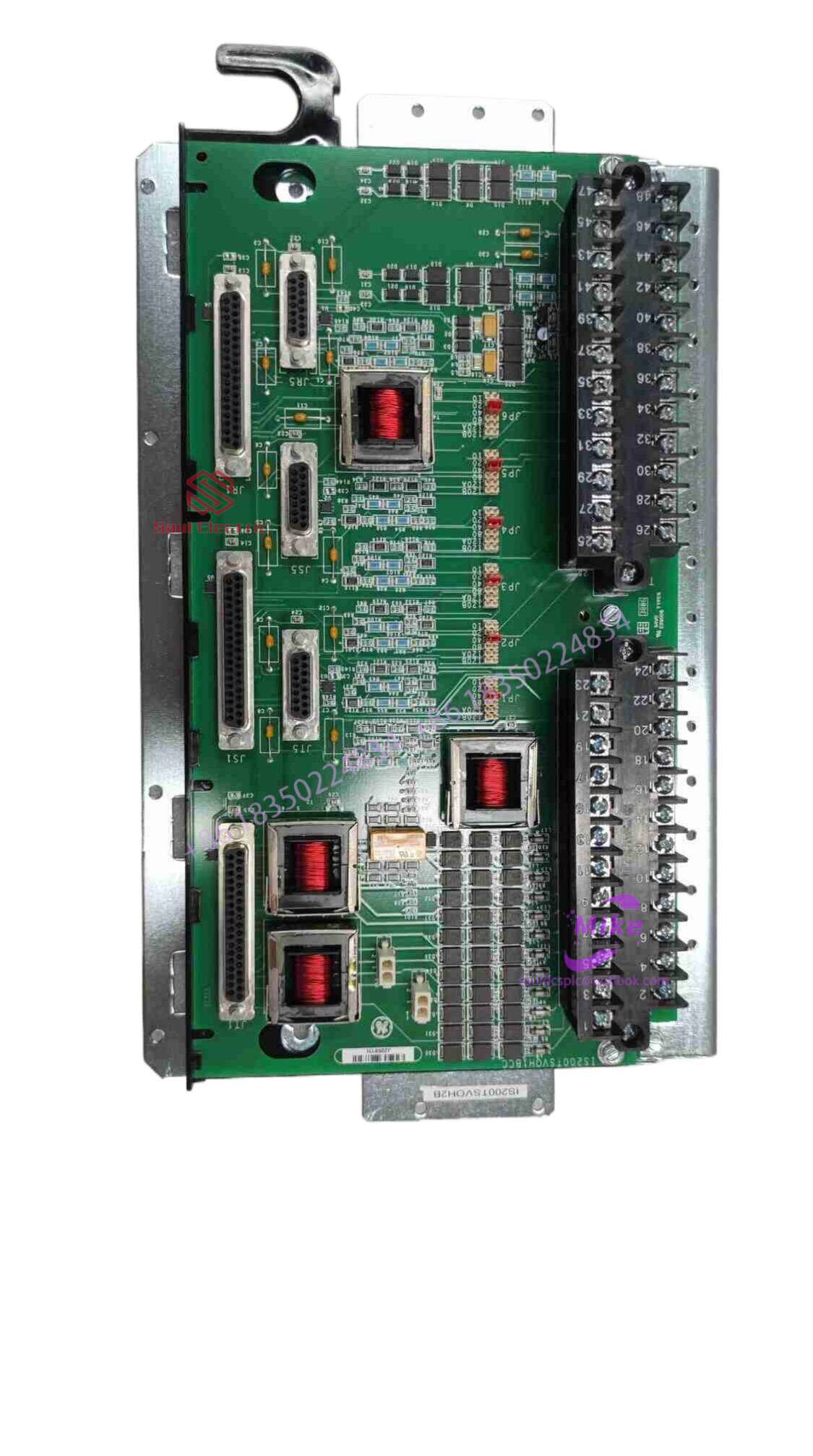
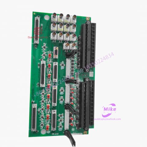
IS200DSPCH 24 channel output module
IS200DSPCH Product Introduction
Basic Information
Brand: GE (General Electric)
Model:IS200DSPCH
Part Number: IS200DSPCH
Series: Mark VIe Speedtronic Turbine Control System I/O Pack
Country of Origin: United States
Product Type: Discrete Input Module (Contact Input Module), also known as PDIA I/O Pack
 Functional Overview
The IS200DSPCH is a 24-channel discrete (digital) input module in the GE Mark VIe control system. Its primary function is to collect discrete signals (contact open/close signals) generated by field devices such as sensors,
switches, and relays, convert them into digital signals that can be recognized and processed by the PLC or control system CPU,
and transmit the processed data to the GE Speedtronic turbine control system or other control equipment, enabling automated control and monitoring. Key Technical Specifications
Rated Voltage: 24.0 VDC (Nominal)
Maximum Rated Voltage: 28.6 VDC
Maximum Rated Contact Input Voltage: 32 VDC
Number of Input Channels: 24 Discrete Inputs
Operating Temperature Range: -30°C to +65°C
Environmental Adaptability: Passes rigorous environmental testing, capable of long-term stable operation in harsh industrial environments Compatible Terminal Boards
The IS200DSPCH can be paired with a variety of GE terminal boards, including but not limited to:
IS200STCIH1A / IS200STCIH2A
IS200STCIH8A
IS200TBCIH2C / IS200TBCIH4C
IS400STCIH1A / IS400STCIH2A / IS400STCIH8A
IS400TBCIH2C Certifications and Safety
This module is UL certified and can be used in both hazardous and non-hazardous locations. The UL certification covers various classes and divisions, and relevant UL mark documents are available for reference.
Detailed explanation of the registers of ADC and touch screen controller
ADCCON: ADC control register (see Figure 6-9)
ENABLE_START:
Set to 1: Start ADC conversion
Set to 0: No operation
RESR_START:
Set to 1: Allow reading operation to start ADC conversion
Set to 0: Disable reading operation Start ADC conversion
STDBM:
Set to 1: Set ADC to idle state (mode)
Set to 0: Set ADC to normal operating state
SEL_MUX: Select the ADC channel that needs to be converted
PRSCVL: ADC conversion clock prescaler parameter
PRSCEN: ADC conversion clock Enable
ECFLG: ADC conversion completion flag bit (read-only)
is 1: ADC conversion is completed
is 0: ADC conversion is in progress
Figure 6-9
ADCTSC: Touch screen control register (see Figure 6-10)
XY_PST: Select the X/Y axis manual measurement mode
AUTO_PST: X/Y axis automatic conversion mode enable bit
PULL_UP: XP end pull-up resistor enable
bit nXPON output status
XM_SEN: Set XMON output status
YP_SEN: Set nYPON output status
YM_SEN: Set YMON output status
Figure 6-10
ADCDLY: ADC conversion cycle waiting timer (see Figure 6-11)
ADCDAT0: ADC data register 0 (see Figure 6-12)
XPDATA: X-axis conversion data register
XY_PST: Select X/Y-axis automatic conversion mode
AUTO_PST: X/Y-axis automatic conversion enable bit UPDOWN: Select the type
of interrupt wait mode
0: An interrupt is generated when pressed
. 1: An interrupt is generated when released.
Figure 6-12
ADCDAT1: The definition of ADC data register 1 (see Figure 6-13)
is similar to ADCDAT0.

There are no reviews yet.