
 HONG KONG SAUL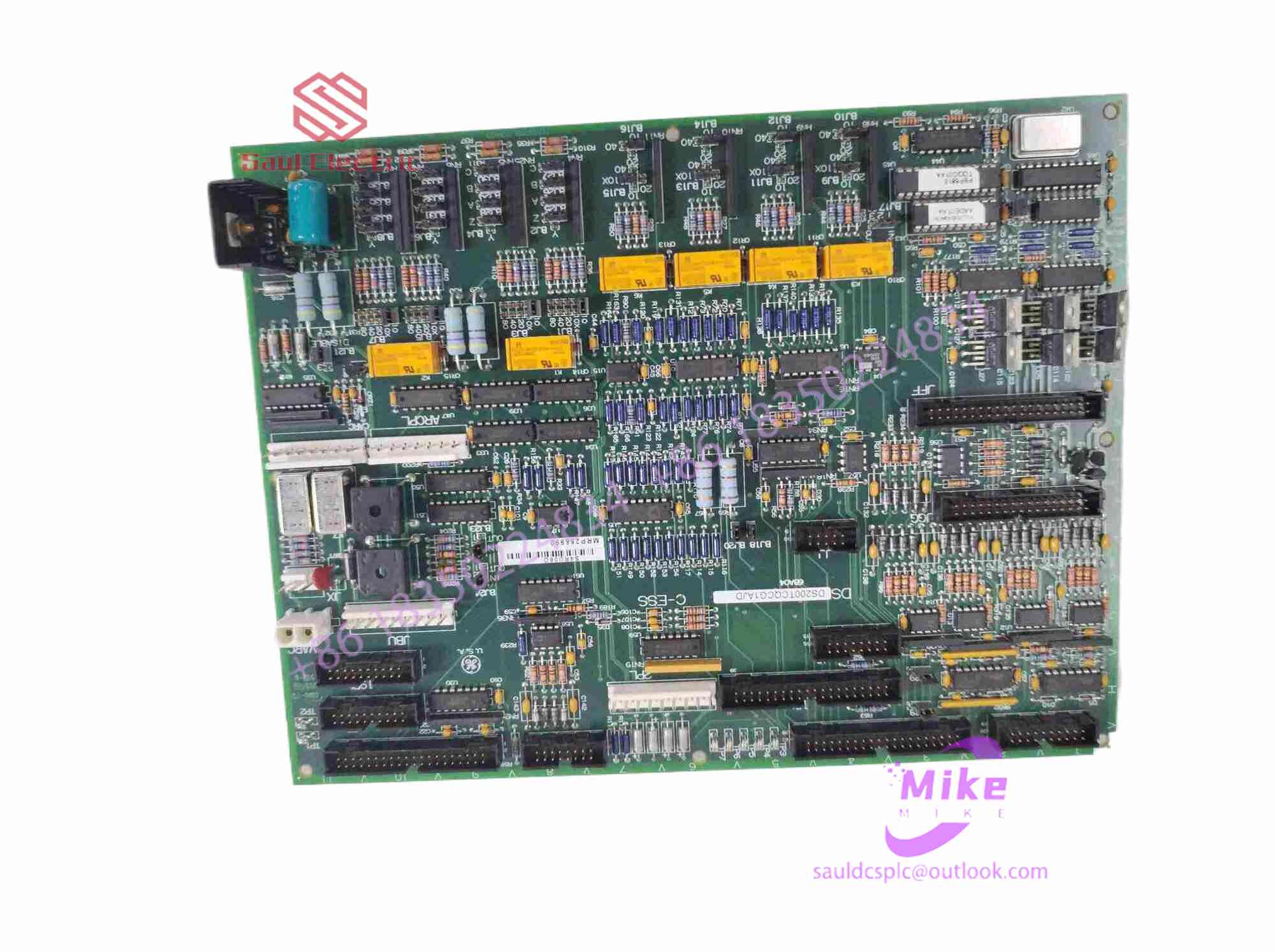

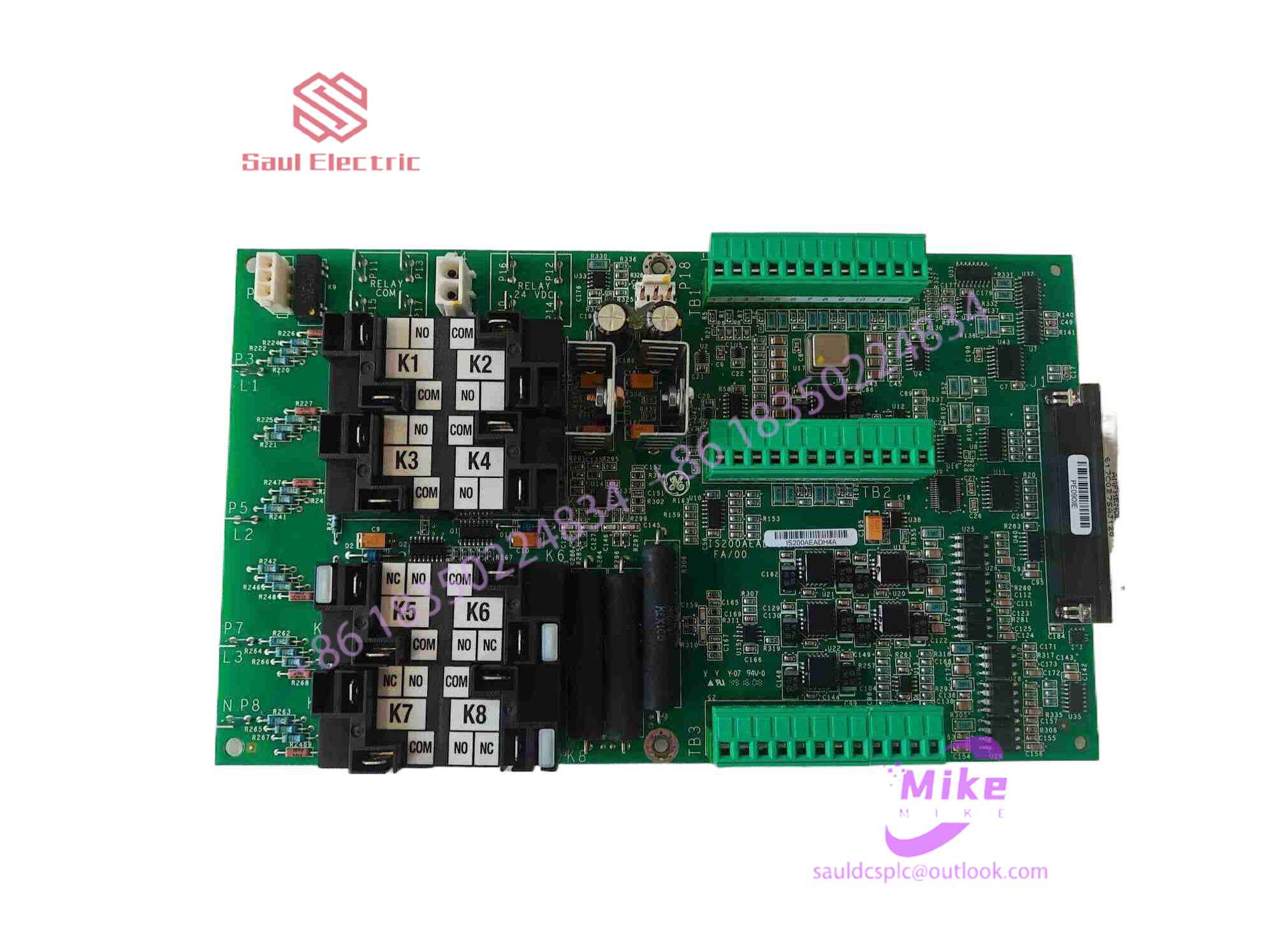
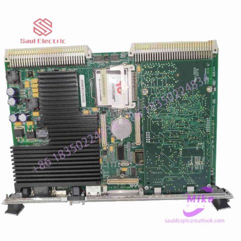
IS200GGXDG1ABB 24 channel output module
IS200GGXDG1ABB Product Introduction
Basic Information
Brand: GE (General Electric)
Model:IS200GGXDG1ABB
Part Number: IS200GGXDG1ABB
Series: Mark VIe Speedtronic Turbine Control System I/O Pack
Country of Origin: United States
Product Type: Discrete Input Module (Contact Input Module), also known as PDIA I/O Pack
 Functional Overview
The IS200GGXDG1ABB is a 24-channel discrete (digital) input module in the GE Mark VIe control system. Its primary function is to collect discrete signals (contact open/close signals) generated by field devices such as sensors,
switches, and relays, convert them into digital signals that can be recognized and processed by the PLC or control system CPU,
and transmit the processed data to the GE Speedtronic turbine control system or other control equipment, enabling automated control and monitoring. Key Technical Specifications
Rated Voltage: 24.0 VDC (Nominal)
Maximum Rated Voltage: 28.6 VDC
Maximum Rated Contact Input Voltage: 32 VDC
Number of Input Channels: 24 Discrete Inputs
Operating Temperature Range: -30°C to +65°C
Environmental Adaptability: Passes rigorous environmental testing, capable of long-term stable operation in harsh industrial environments Compatible Terminal Boards
The IS200GGXDG1ABB can be paired with a variety of GE terminal boards, including but not limited to:
IS200STCIH1A / IS200STCIH2A
IS200STCIH8A
IS200TBCIH2C / IS200TBCIH4C
IS400STCIH1A / IS400STCIH2A / IS400STCIH8A
IS400TBCIH2C Certifications and Safety
This module is UL certified and can be used in both hazardous and non-hazardous locations. The UL certification covers various classes and divisions, and relevant UL mark documents are available for reference.
In the formula, a is the design acceleration/deceleration value: s is the current actual position value of the elevator: V2 is the maximum speed of the elevator at this position.
Considering that the lifting system needs to enter the parking track at a low crawling speed when entering the end of the stroke to avoid equipment damage caused by large mechanical impact, therefore, when there are still 1~5m away from the parking position, the lifting speed is limited to 0.5m/ below s.
Since the instantaneous speed before parking is very low, the position accuracy of the system’s parking can be relatively improved, which is particularly important when the auxiliary shaft is lifted.
2.2 Design and implementation of security protection functions
Mines have particularly strict requirements on safety and reliability of hoist control systems [5]. While ensuring high reliability of electrical control equipment, the control system also sets up multiple protections in key links where failures may occur, and detects the actions and feedback signals of these protection devices in real time.
First of all, monitoring the operating status of the elevator is the top priority in the safety protection function of the elevator control system. In the control system, the operating speed and position of the motor are monitored at all times, and the current position and speed values are compared with the system’s designed speed and position curve. Once it is found that the actual operating speed of the hoist exceeds the designed speed value, immediately Issue an emergency stop command and strictly ensure that the lifting speed is within the safe monitoring range during the entire lifting process. At the same time, position detection switches are arranged at several locations in the wellbore, and these position detection switches correspond to specific position values and corresponding speed values. When the elevator passes these switches, if it is found through encoder detection that the actual speed value and position deviate from the values corresponding to the position detection switch, the control system will also judge that it is in a fault state and immediately implement an emergency stop.
In order to determine whether the encoder connected to the main shaft of the elevator drum is normal, two other encoders are installed on the elevator. In this way, the position and speed detection values of the three encoders are always compared. Once it is found that the deviation between the detection value of one encoder and the detection value of the other two encoders exceeds the allowable range, the control system will immediately consider it to have entered a fault state and implement an emergency stop. Protective action.
3 Conclusion
The efficient and safe operation of main well equipment is an important guarantee for its function. In the application of mine hoist, the 800xA system designed speed curve, self-correction, various self-diagnosis and protection functions according to the specific process characteristics of the main shaft mine hoist, which has achieved good results in practical applications.

There are no reviews yet.