
 HONG KONG SAUL
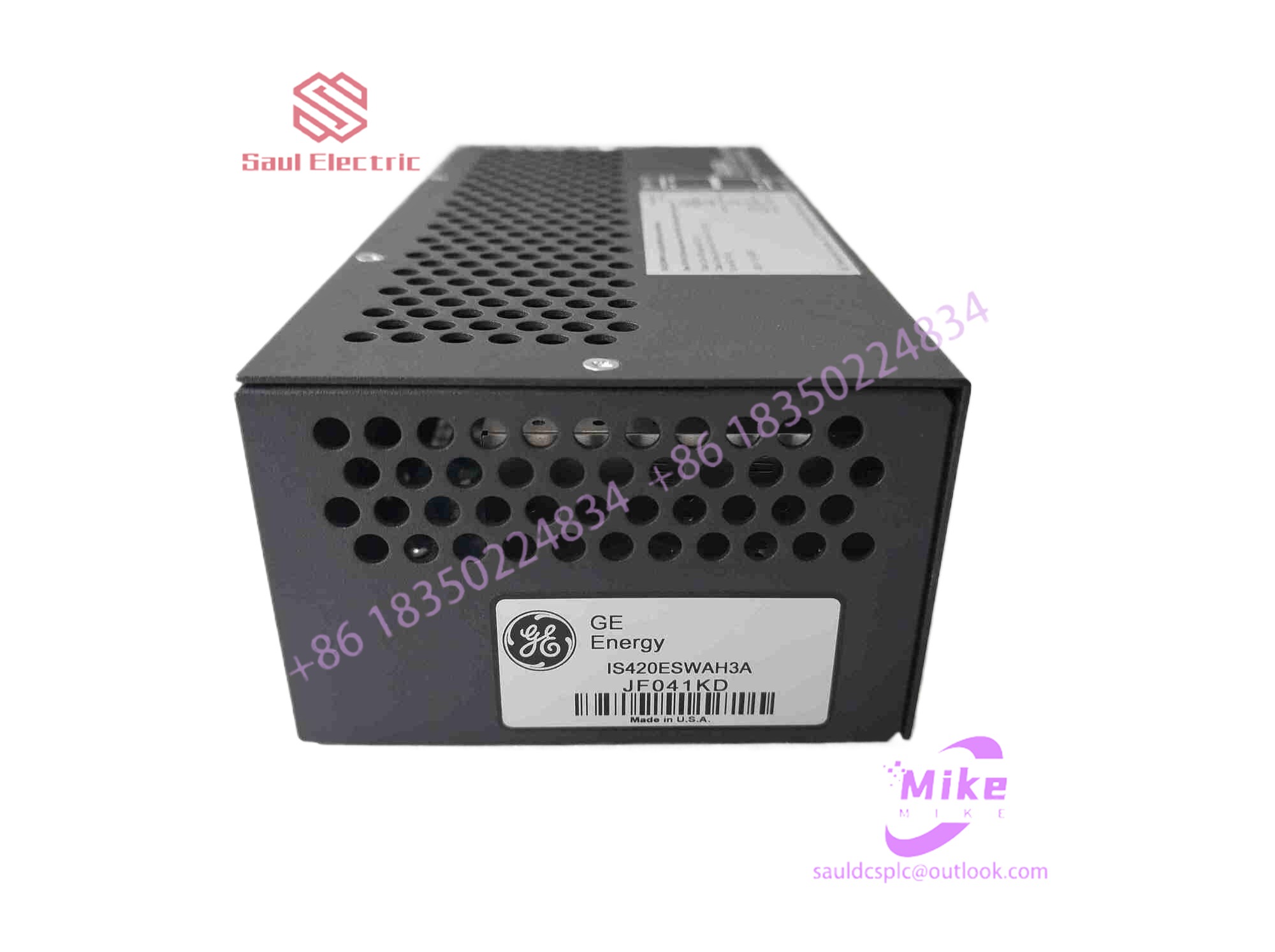
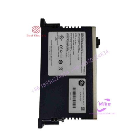
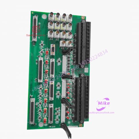
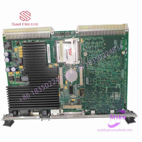
IS200IGDMH1AAA 24 channel output module
IS200IGDMH1AAA Product Introduction
Basic Information
Brand: GE (General Electric)
Model:IS200IGDMH1AAA
Part Number: IS200IGDMH1AAA
Series: Mark VIe Speedtronic Turbine Control System I/O Pack
Country of Origin: United States
Product Type: Discrete Input Module (Contact Input Module), also known as PDIA I/O Pack
 Functional Overview
The IS200IGDMH1AAA is a 24-channel discrete (digital) input module in the GE Mark VIe control system. Its primary function is to collect discrete signals (contact open/close signals) generated by field devices such as sensors,
switches, and relays, convert them into digital signals that can be recognized and processed by the PLC or control system CPU,
and transmit the processed data to the GE Speedtronic turbine control system or other control equipment, enabling automated control and monitoring. Key Technical Specifications
Rated Voltage: 24.0 VDC (Nominal)
Maximum Rated Voltage: 28.6 VDC
Maximum Rated Contact Input Voltage: 32 VDC
Number of Input Channels: 24 Discrete Inputs
Operating Temperature Range: -30°C to +65°C
Environmental Adaptability: Passes rigorous environmental testing, capable of long-term stable operation in harsh industrial environments Compatible Terminal Boards
The IS200IGDMH1AAA can be paired with a variety of GE terminal boards, including but not limited to:
IS200STCIH1A / IS200STCIH2A
IS200STCIH8A
IS200TBCIH2C / IS200TBCIH4C
IS400STCIH1A / IS400STCIH2A / IS400STCIH8A
IS400TBCIH2C Certifications and Safety
This module is UL certified and can be used in both hazardous and non-hazardous locations. The UL certification covers various classes and divisions, and relevant UL mark documents are available for reference.
3Configuring Siemens PLC
For PLC, Siemens S-1200PLC is used. Siemens PLC needs to be configured and programmed in Botu software. After the program is completed, the communication settings between the robot and PLC can be set. First, select the device and network in the Porto software, then add a new device and select the controller model as Siemens 1212, as shown in Figure 5. After adding the device, you need to set up the PLC network. The computer and PLC must set corresponding IP addresses in the same network segment to facilitate downloading and uploading PLC programs. After the settings are completed, click on the project tree on the left to select the program block, and then enter program writing. After the entire program is written, you can check whether the robot has received the signal from the PLC through the input and output menu call in the ABB industrial robot teaching pendant, or you can check online whether the PLC has received the signal from the robot through the Botu software. When the line connection is good, the operator can set some signals to complete the test work. If the test communication is normal, further PLC programming can be performed.
Figure 5 Botu software configures new equipment
4 Conclusion
This article explains in detail the communication setting process between ABB industrial robots and Siemens PLC, making full use of the characteristics of industrial fieldbus technology. During the communication process, signal settings are based on DeviceNet fieldbus technology. The actual operation verifies the content described in this article. feasibility. In communication settings, special attention should be paid to the process of setting parameters such as address signals. Based on DeviceNet fieldbus technology, communication between ABB industrial robots and PLCs can be completed more quickly and conveniently.
In modern industry, the communication technology between industrial robots and PLC has improved the level of production line automation and can better utilize the flexible and expandable characteristics of industrial robots. Therefore, it is foreseeable that the application of communication technology in the production line will continue to increase, thus exerting a great influence on industrial production. greater effect.

There are no reviews yet.