
 HONG KONG SAUL
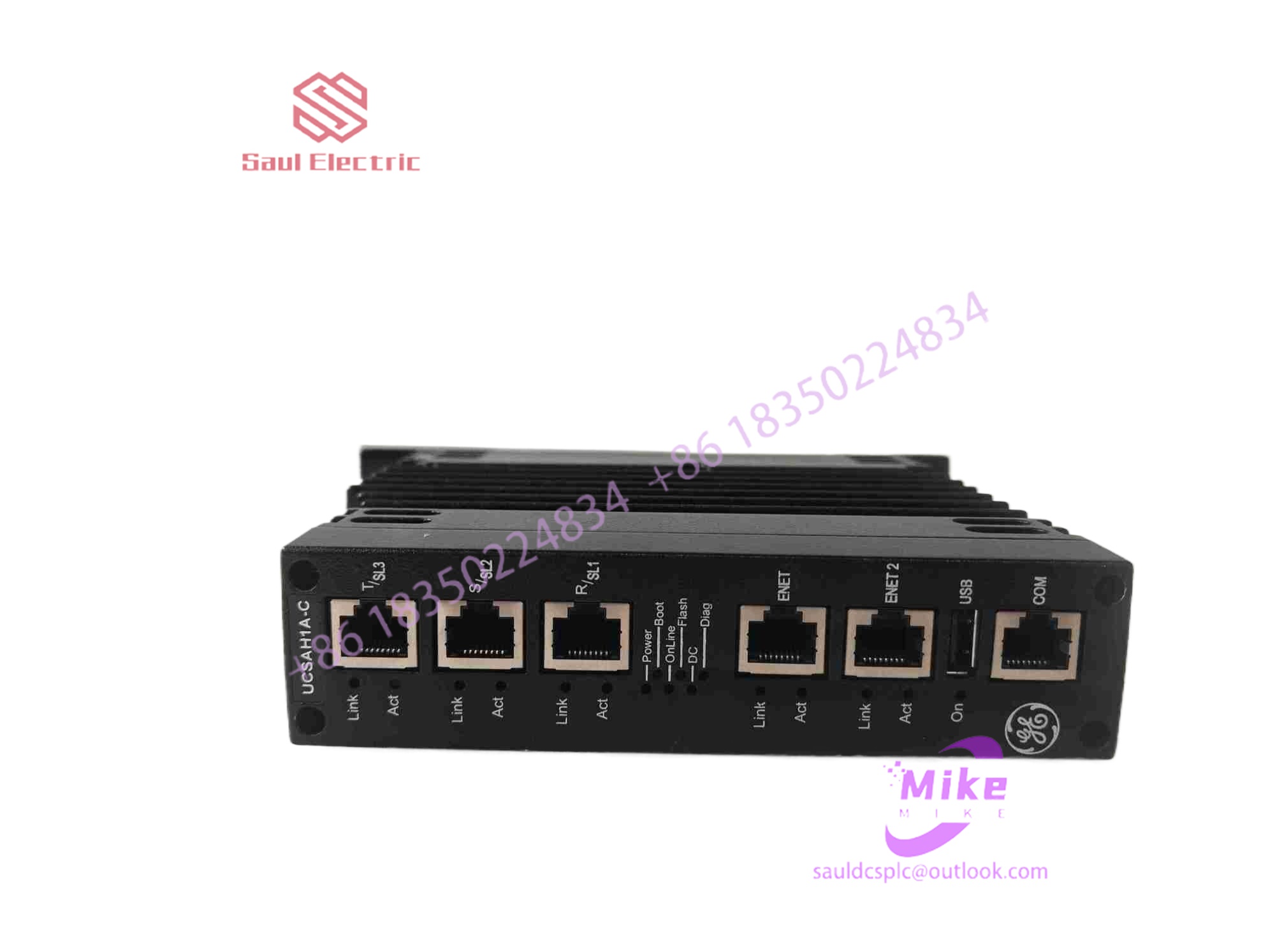
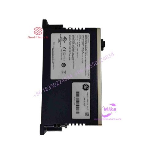
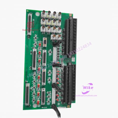
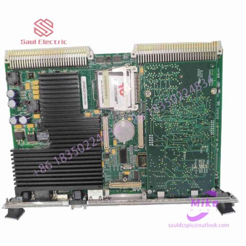
IS200PMCIH1AAA6BA00 integrated circuit board
IS200PMCIH1AAA6BA00 Product Introduction
Basic Information
Brand: GE (General Electric)
Model:IS200PMCIH1AAA6BA00
Part Number: IS200PMCIH1AAA6BA00
Series: Mark VIe Speedtronic Turbine Control System I/O Pack
Country of Origin: United States
Product Type: Discrete Input Module (Contact Input Module), also known as PDIA I/O Pack
contacts: Mike
+86 18350224834 (WeChat/WhatsApp)
Email:Mike18350224834@gmail.com
 Functional Overview
The IS200PMCIH1AAA6BA00 is a 24-channel discrete (digital) input module in the GE Mark VIe control system. Its primary function is to collect discrete signals (contact open/close signals) generated by field devices such as sensors,
switches, and relays, convert them into digital signals that can be recognized and processed by the PLC or control system CPU,
and transmit the processed data to the GE Speedtronic turbine control system or other control equipment, enabling automated control and monitoring. Key Technical Specifications
Rated Voltage: 24.0 VDC (Nominal)
Maximum Rated Voltage: 28.6 VDC
Maximum Rated Contact Input Voltage: 32 VDC
Number of Input Channels: 24 Discrete Inputs
Operating Temperature Range: -30°C to +65°C
Environmental Adaptability: Passes rigorous environmental testing, capable of long-term stable operation in harsh industrial environments Compatible Terminal Boards
The IS200PMCIH1AAA6BA00 can be paired with a variety of GE terminal boards, including but not limited to:
IS200STCIH1A / IS200STCIH2A
IS200STCIH8A
IS200TBCIH2C / IS200TBCIH4C
IS400STCIH1A / IS400STCIH2A / IS400STCIH8A
IS400TBCIH2C Certifications and Safety
This module is UL certified and can be used in both hazardous and non-hazardous locations. The UL certification covers various classes and divisions, and relevant UL mark documents are available for reference.
Design challenge three
Touch buttons, touch sliders and touch pads all use copper foil as touch sensors, but touch screens basically use ITO (Indium Tin Oxides) material as the touch sensing layer. The resistivity of copper foil is extremely small, so its resistance is almost negligible. ITO is transparent and conductive, but ITO has a relatively high resistivity. Usually the resistivity of ITO is expressed as square resistance on touch screens, that is, the resistance of a unit square. Generally, the sheet resistance of ITO ranges from 45 to 350 ohms, depending on the coating process of the touch screen manufacturer. Due to the existence of ITO resistors, there will be a resistance of 3K~30K ohms at the near end and far end of each sensing strip on the touch screen. This resistance combined with the RC delay generated by the self-capacitance on each sensing strip makes the induction The near and far ends of the bar will have different response times or charge and discharge times for the emitted signals, which will lead to different sizes of finger touch signals at the near and far ends. In severe cases, this difference can reach more than 50%. How to eliminate or reduce this difference is the third challenge in multi-point capacitive touch screen design. Although choosing an ITO coating with lower sheet resistance is the most direct way to reduce this difference, usually the thickness of ITO coating with lower sheet resistance will be thicker, resulting in a decrease in transparency and an increase in cost. This is unacceptable to many end customers.
Design challenge four
Signal-to-noise ratio (SNR) is one of the most important indicators in multi-point capacitive touch screen design. For a touch screen, it is not enough to have a large enough finger signal. In fact, the touch screen is not in an ivory tower, and there are many noise sources around it. For example, the LCD immediately below it is a noise source. Different LCDs and even different display screens have different noise sizes and spectra. Especially for some AC Vcomm type LCDs, it can produce current noise up to 15nA/mm2 and voltage noise above 1V on the surface of the LCD. Although the solution of placing an ITO shielding layer under the touch screen has been adopted by some designers, the increase in the shielding layer leads to an increase in the thickness and cost of the touch screen, which also affects visibility to a certain extent. Not all end customers may accept this. The radio frequency signal of the mobile phone itself and the electromagnetic waves from the outside will also interfere with it. When a terminal with a touch screen is powered by external mains power, a large amount of common mode noise may be generated from the power grid and power adapter. There are also troublesome charger noise, noise generated by the touch screen and the system itself, such as AD conversion noise, switching noise, power supply noise and 8 kV ESD noise used in ESD testing. In such a noisy environment, how to make the touch screen system have good noise immunity to noise from various noise sources and obtain a high enough signal-to-noise ratio is the fourth challenge in multi-point capacitive touch screen design.

There are no reviews yet.