
 HONG KONG SAUL
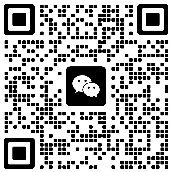
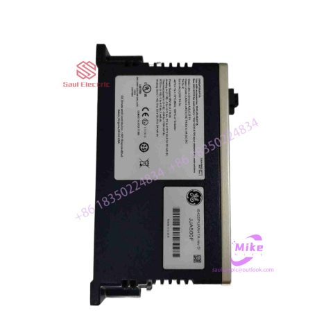
IS200STCIH6AED Turbine Control System
IS200STCIH6AED Product Introduction
Basic Information
Brand: GE (General Electric)
Model:IS200STCIH6AED
Part Number: IS200STCIH6AED
Series: Mark VIe Speedtronic Turbine Control System I/O Pack
Country of Origin: United States
Product Type: Discrete Input Module (Contact Input Module), also known as PDIA I/O Pack
contacts: Mike
+86 18350224834 (WeChat/WhatsApp)
Email:Mike18350224834@gmail.com
 Functional Overview
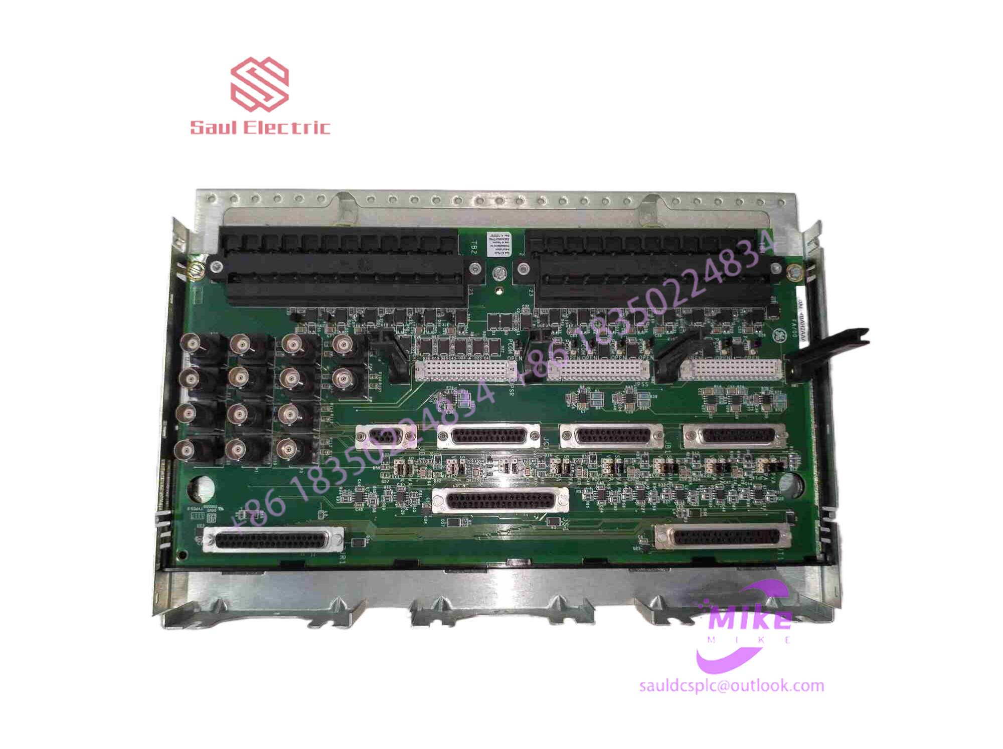
The IS200STCIH6AED is a 24-channel discrete (digital) input module in the GE Mark VIe control system. Its primary function is to collect discrete signals (contact open/close signals) generated by field devices such as sensors,
switches, and relays, convert them into digital signals that can be recognized and processed by the PLC or control system CPU,
and transmit the processed data to the GE Speedtronic turbine control system or other control equipment, enabling automated control and monitoring. Key Technical Specifications
Rated Voltage: 24.0 VDC (Nominal)
Maximum Rated Voltage: 28.6 VDC
Maximum Rated Contact Input Voltage: 32 VDC
Number of Input Channels: 24 Discrete Inputs
Operating Temperature Range: -30°C to +65°C
Environmental Adaptability: Passes rigorous environmental testing, capable of long-term stable operation in harsh industrial environments Compatible Terminal Boards
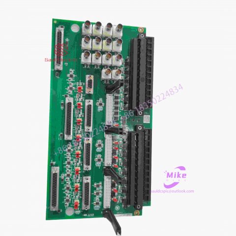
The IS200STCIH6AED can be paired with a variety of GE terminal boards, including but not limited to:
IS200STCIH1A / IS200STCIH2A
IS200STCIH8A
IS200TBCIH2C / IS200TBCIH4C
IS400STCIH1A / IS400STCIH2A / IS400STCIH8A
IS400TBCIH2C Certifications and Safety
This module is UL certified and can be used in both hazardous and non-hazardous locations. The UL certification covers various classes and divisions, and relevant UL mark documents are available for reference.
Design and implementation of variable frequency transmission system based on ABB hardware architecture
introduction
With the increasing development of transmission technology and the increasing demand for actual use, variable frequency transmission systems have been widely used.
As a Fortune 500 company in the world, ABB is a leader in the fields of power and automation technology and has strong capabilities in control systems, high-voltage, medium-voltage and low-voltage frequency conversion technology and transmission technology. Therefore, this article mainly relies on ABB’s control, frequency conversion and transmission technology, and uses related hardware products to design and implement the frequency conversion transmission system.
To truly design and implement a usable variable frequency drive system, the entire system must be fully equipped, conveniently operable and compatible with a wide range of needs, so that it can be used without changing the control method and operation. According to the actual control needs, that is, combining frequency converters with different performances and variable frequency motors with different speeds or torques to quickly build and realize a variety of control requirements.
1 System design purpose and composition
The design purpose of this system is to control ABB inverters through local and remote control methods and complete 4 independent channels of closed-loop speed control to drive different test objects to rotate.
The entire control system consists of the following four main components: remote control computer, panel industrial computer (touch screen), PLC and speed-regulating frequency converter. The system design block diagram is shown in Figure 1.
In order to ensure the accuracy of motor speed control, an encoder module is added. The PLC can obtain the feedback of the rotary encoder in the frequency converter through the ProfibusDP protocol. The speed control is performed through the frequency converter for internal PID closed-loop control.
2 System hardware implementation
2.1 Control some hardware
The control part of the hardware mainly refers to the sum of hardware that supports operators to use the equipment directly or indirectly and complete the functions of the equipment. Its main hardware includes computer control terminal, touch screen control terminal, PLC control unit, other auxiliary circuits and measurement and control components.
2.2 Transmission hardware
The transmission hardware mainly refers to the total number of equipment that can relatively independently perform a complete transmission function. Its main hardware includes frequency converters, variable frequency motors (configured with rotary encoders as needed) and other auxiliary circuits. Among them, the selection of motors and frequency converters should be based on the principle of selecting the motor first and then selecting the frequency converter. details as follows:
First, according to the tangential speed at which the object under test is to complete rotation, select the motor speed according to the following formula:
Secondly, choose based on several other important basic parameters of the motor, such as system hardness, torque, weight, etc. This system uses ABB’s variable frequency motor.
Finally, select an appropriate frequency converter based on the motor power. In addition, the actual situation of the object being tested must also be taken into consideration, such as whether the rotating load belongs to the heavy-load usage of the frequency converter, etc.
3Software system
System software includes three major categories in total, namely computer control software, touch screen software and PLC software. Among them, the PLC software, as the underlying software, is responsible for the interaction with the computer control software and touch screen software on the upper side, and the interaction with the frequency converter on the lower side. Therefore, from the architecture of the entire software system, it can be defined as a host and slave computer structure.
3.1 System development platform
The software system has two control methods: remote and local. The development platforms for the three major categories of software are Windows operating system, LabVIEW[4] integrated development environment, CodesysV2.3, and CP400.
3.2 System software architecture
The software of the entire system is divided into three types, namely remote control software, PLC control software and local control software. Among them, the remote control software runs under the Windows operating system and is developed under the LabVIEW integrated development environment; the PLC control software is developed under the CodesysV2.3 programming environment; the local control software runs on the touch screen computer and is developed under the CP400 environment. The relationship between the three software is shown in Figure 2.
There are no reviews yet.