
 HONG KONG SAUL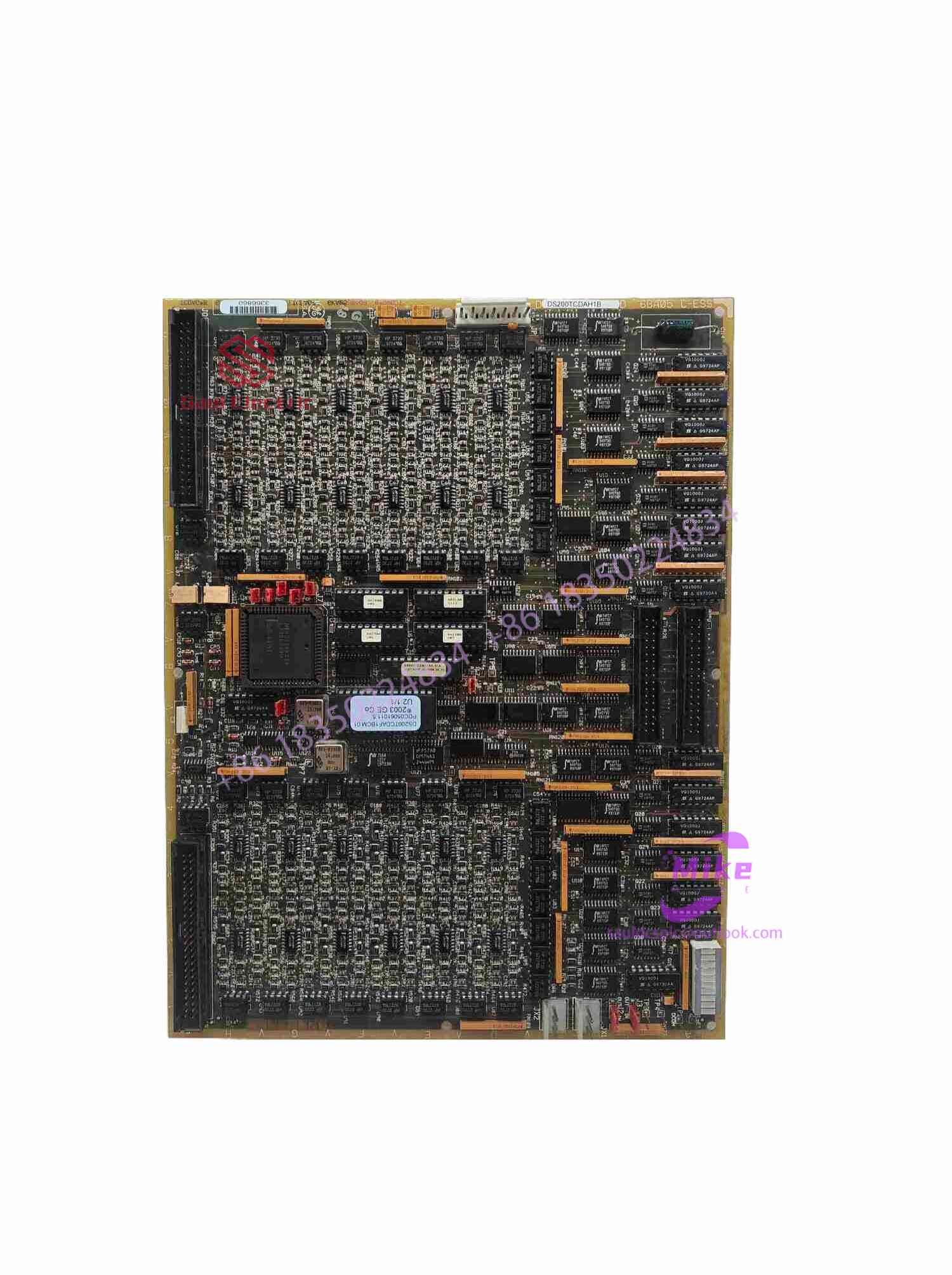
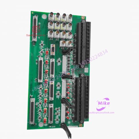
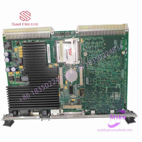
IS215UCCCM04A 24 channel output module
IS215UCCCM04A Product Introduction
Basic Information
Brand: GE (General Electric)
Model:IS215UCCCM04A
Part Number: IS215UCCCM04A
Series: Mark VIe Speedtronic Turbine Control System I/O Pack
Country of Origin: United States
Product Type: Discrete Input Module (Contact Input Module), also known as PDIA I/O Pack
contacts: Mike
+86 18350224834 (WeChat/WhatsApp)
Email:Mike18350224834@gmail.com
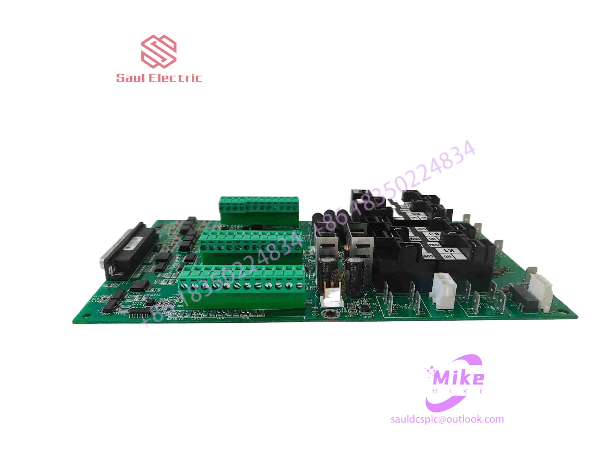 Functional Overview
The IS215UCCCM04A is a 24-channel discrete (digital) input module in the GE Mark VIe control system. Its primary function is to collect discrete signals (contact open/close signals) generated by field devices such as sensors,
switches, and relays, convert them into digital signals that can be recognized and processed by the PLC or control system CPU,
and transmit the processed data to the GE Speedtronic turbine control system or other control equipment, enabling automated control and monitoring. Key Technical Specifications
Rated Voltage: 24.0 VDC (Nominal)
Maximum Rated Voltage: 28.6 VDC
Maximum Rated Contact Input Voltage: 32 VDC
Number of Input Channels: 24 Discrete Inputs
Operating Temperature Range: -30°C to +65°C
Environmental Adaptability: Passes rigorous environmental testing, capable of long-term stable operation in harsh industrial environments Compatible Terminal Boards
The IS215UCCCM04A can be paired with a variety of GE terminal boards, including but not limited to:
IS200STCIH1A / IS200STCIH2A
IS200STCIH8A
IS200TBCIH2C / IS200TBCIH4C
IS400STCIH1A / IS400STCIH2A / IS400STCIH8A
IS400TBCIH2C Certifications and Safety
This module is UL certified and can be used in both hazardous and non-hazardous locations. The UL certification covers various classes and divisions, and relevant UL mark documents are available for reference.
How to use other electronic devices to realize the design of resistive touch screen?
Touch screens are increasingly used in various fields of national production to realize handwriting input, query, control, etc. These touch screens are mostly installed on monitors (CRT) or liquid crystals (LCD), and there are more and more types of touch screens. There are vector pressure sensing technology touch screens, resistive technology touch screens, capacitive technology touch screens, infrared technology touch screens, surface acoustic wave technology touch screens, etc. Each of these touch screens has its own advantages and disadvantages. There are many articles on them, so I will not go into details here. This article mainly introduces the correction principle, algorithm and programming application design of the resistive technology touch screen installed on the LCD.
2.1 Overview
As we all know, touch screens based on resistive technology are divided into four-wire resistive touch screens, five-wire resistive touch screens or more-wire resistive touch screens. However, no matter which type of resistive touch screen, there is one biggest commonality: the voltage is linearly and uniformly distributed. It is precisely because of this feature that the touch screen is very convenient to calibrate and use. Speaking of touch screen calibration, some people may ask why the touch screen needs to be calibrated? We know that the performance of the touch screen itself will be somewhat different, and the position will inevitably deviate when installed on the LCD or CRT. In addition, after using it for a period of time, The performance parameters of the touch screen may also change. Therefore, when we use different touch screens, it is difficult to guarantee that we will get the same touch coordinates even if we touch the same position on the display screen. This makes it difficult for programmers to use the same program to manage and control the touch screen. It is for this reason that we introduced the concept of calibration so that programmers using touch screen devices can use a unified procedure to manage the touch screen.
2.2 Five-point method to calibrate touch screen
2.2.1 Physical coordinates and logical coordinates
In order to facilitate understanding, we first introduce two concepts, coordinates and logical coordinates. The physical coordinates are the actual positions of the points on the touch screen, which we usually measure by the number of points on the liquid crystal. Logical coordinates are the coordinate values after A/D conversion when this point on the touch screen is touched. As shown in the figure below, we assume that the lower left corner of the liquid crystal is the origin of the coordinate axis A. We pick another point B on the liquid crystal (the center of the cross line intersection). B is 10 points away from A in the X direction and 20 points away from A in the Y direction. Then Let’s just say that the physical coordinates of this point on the touch screen opposite point B on the liquid crystal are (10, 20). If the X-to-A/D conversion value we get when we touch this point is 100, and the Y-to-A/D conversion value is 200, we say that the logical coordinates of this point are (100, 200).
2.2.2 Calculation of logical coordinates
Since the voltage of the resistive touch screen is linearly and uniformly distributed, the coordinates after A/D conversion are also linear. If we set the point on the touch screen corresponding to the lower left corner of the liquid crystal as the physical coordinate origin A, its physical coordinates are marked as (XA=0, YA=0) and its logical coordinates are marked as (XLA, YLA) (not necessarily 0). Then the logical coordinates of any point B on the touch screen can be expressed as:

There are no reviews yet.