
 HONG KONG SAUL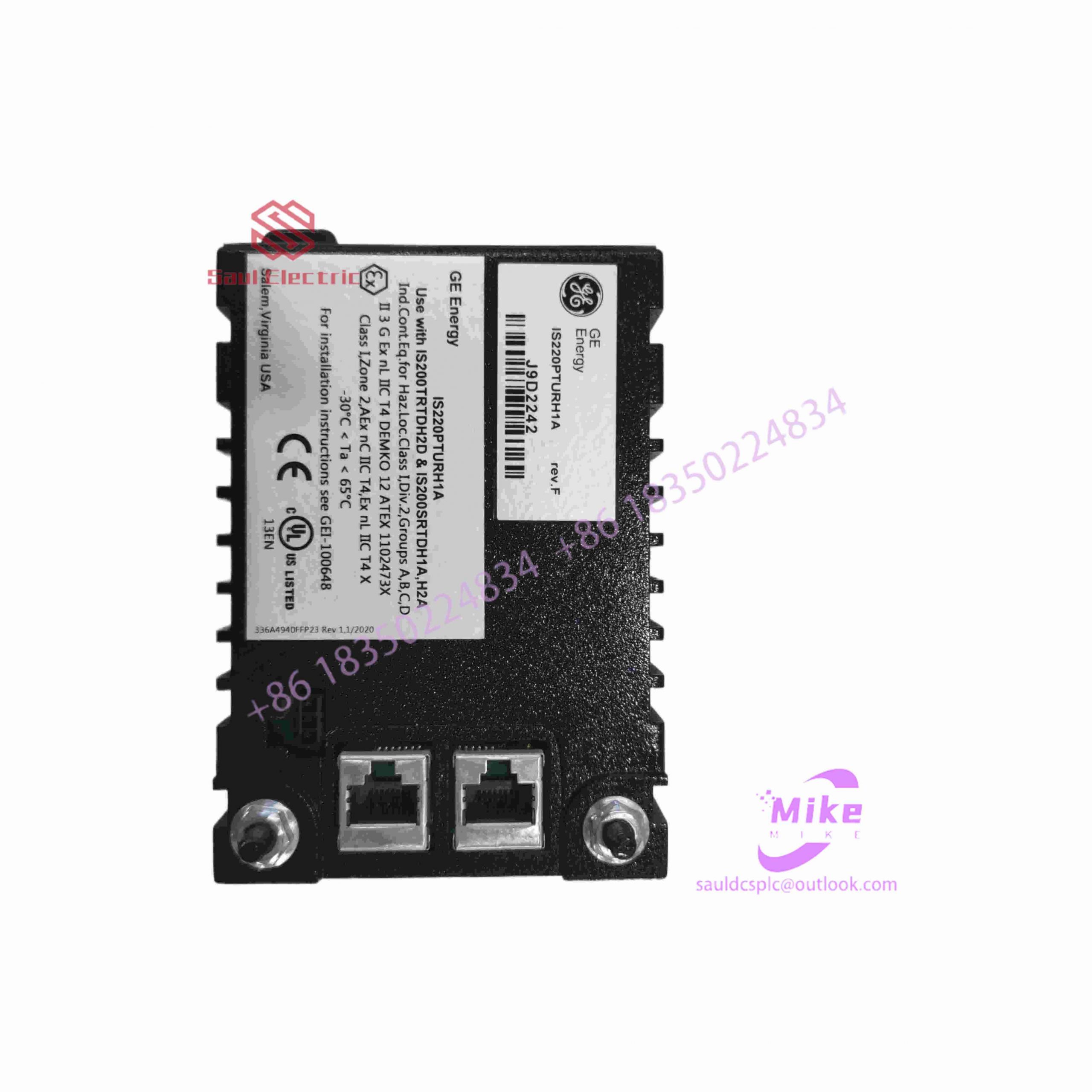

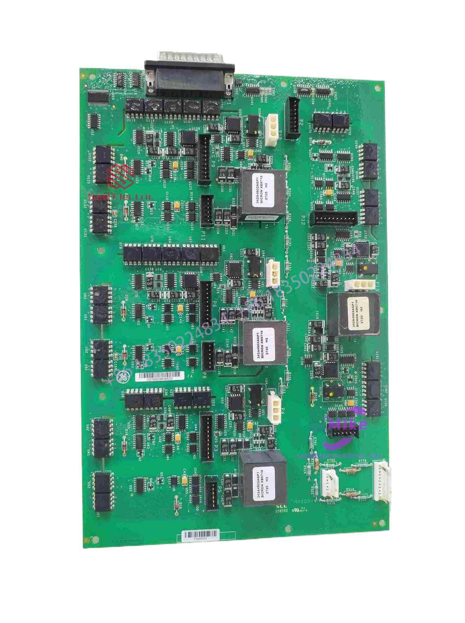
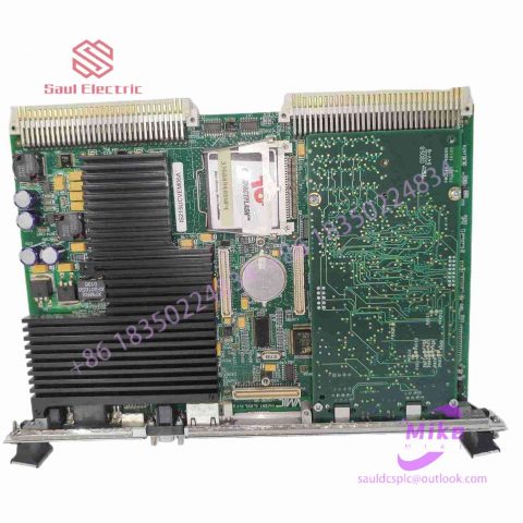
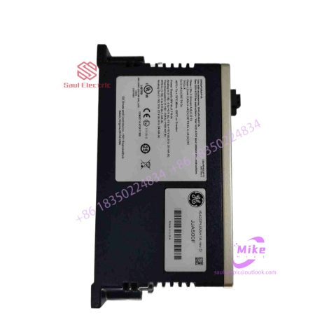
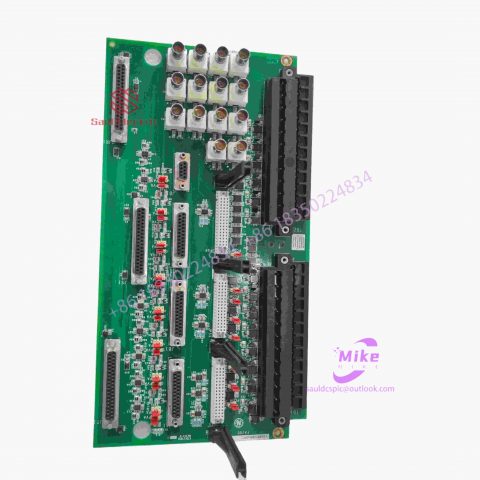
IS215UCVEM09 integrated circuit board
IS215UCVEM09 Product Introduction
Basic Information
Brand: GE (General Electric)
Model:IS215UCVEM09
Part Number: IS215UCVEM09
Series: Mark VIe Speedtronic Turbine Control System I/O Pack
Country of Origin: United States
Product Type: Discrete Input Module (Contact Input Module), also known as PDIA I/O Pack
 Functional Overview
The IS215UCVEM09 is a 24-channel discrete (digital) input module in the GE Mark VIe control system. Its primary function is to collect discrete signals (contact open/close signals) generated by field devices such as sensors,
switches, and relays, convert them into digital signals that can be recognized and processed by the PLC or control system CPU,
and transmit the processed data to the GE Speedtronic turbine control system or other control equipment, enabling automated control and monitoring. Key Technical Specifications
Rated Voltage: 24.0 VDC (Nominal)
Maximum Rated Voltage: 28.6 VDC
Maximum Rated Contact Input Voltage: 32 VDC
Number of Input Channels: 24 Discrete Inputs
Operating Temperature Range: -30°C to +65°C
Environmental Adaptability: Passes rigorous environmental testing, capable of long-term stable operation in harsh industrial environments Compatible Terminal Boards
The IS215UCVEM09 can be paired with a variety of GE terminal boards, including but not limited to:
IS200STCIH1A / IS200STCIH2A
IS200STCIH8A
IS200TBCIH2C / IS200TBCIH4C
IS400STCIH1A / IS400STCIH2A / IS400STCIH8A
IS400TBCIH2C Certifications and Safety
This module is UL certified and can be used in both hazardous and non-hazardous locations. The UL certification covers various classes and divisions, and relevant UL mark documents are available for reference.
Design of ABB industrial robot deburring and grinding workstation based on RobotStudio simulation software
introduction
As an official offline programming software for ABB robots, Robotstudio not only has powerful simulation and offline programming functions, but also has automatic path generation function and simulation monitoring collision function. It can realize the simulation of robots in real scenes, so as to timely update existing robot programs. optimize. On-site teaching programming will affect normal production activities on site.
The application of Robotstudio software offline programming can reduce on-site teaching and programming time.
As a traditional process of mechanical processing, deburring and grinding have a wide range of applications. However, for a long time, in the process of manual deburring and polishing, there have been differences in operations between workers. The manual operation is not repeatable and the deburring effect is unstable, which has seriously affected the surface quality and service life of the finished product; and the working environment There is a large amount of dust floating in the air and the conditions are harsh, seriously endangering the physical and mental health of workers. With the proposal of “Made in China 2025”, intelligent manufacturing production has become an important development direction for the transformation and upgrading of the future manufacturing industry. The use of industrial robot automated production lines for repetitive batch processing operations can not only greatly improve production efficiency, but also greatly improve product quality. Yield and production stability. Therefore, before designing the robot polishing program, if the shape, size and polishing amount of the workpiece to be polished are known, the robot offline program can be written on the Robotstudio software according to the existing conditions, thereby improving the efficiency of on-site programming.
1Design task description
This task is to create a new simulation workstation in ABB robot simulation software Robotstudio. The corresponding training equipment in reality is the Yalong YL-l360A industrial robot deburring and grinding system control and application equipment. The industrial robot selection and method of the simulation workstation are The grinding head installed on the blue plate refers to the Yalong YL-l360A industrial robot deburring and grinding system control and application equipment, and the workpiece is customized. The ABB industrial robot deburring and grinding workstation simulation training process includes: creating a workstation, setting up tools, creating smart components, creating tool coordinate systems, creating trajectories, programming, simulation design, and verification.
2 Task implementation
2.1 Create a workstation
Import the robot: First, create a new simulation workstation in the Robotstudio software. The workstation name is self-named, and then import the corresponding industrial robot IRB1410. The robot position remains unchanged by default. Create a robot system, modify the system options, check 709-1DeviceNetMaster/s1ave, select Chinese as the language, and leave the other options unchanged by default, then click Confirm to create the robot system. After the robot system is created, hide the industrial robot IRB1410 to facilitate subsequent workstation operations.
Import workpiece: The workpiece here is customized, and the corresponding workpiece is selected according to the actual situation on site. This article uses the original workpiece Curvet in Robotstudio software. After importing it into the workstation, according to the reachable range of the robot, just place the workpiece at a suitable location within the reachable range of the robot, as shown in Figure 1.
Import the grinding rotor tool: First, create a new grinding rotor tool component – rotor – copy (2) and rotor – copy (2) in the so1idworks 3D software. The rotor – copy (2) is a rotatable grinding rotor. —The copy is the tool body, which is the grinding rotor frame, and is installed on the robot flange, as shown in Figure 2.
2.2 Setting tools
First, move the rotatable grinding rotor and the tool body to the local origin based on point A, and adjust the initial tool angle so that the grinding rotor is parallel to the x-axis of the geodetic coordinate system, as shown in Figure 3. Set the local origin of the tool body at this time, change the position x, y,: to 0, 0, 0, and change the direction x, y,: to 0, 0, 0.
Figure 3 Tool settings
Create a new frame at point B of the tool body, name it “frame l”, and adjust the direction of frame l so that the axis is perpendicular to the plane of point B. The specific direction is shown in Figure 4.

There are no reviews yet.