
 HONG KONG SAUL

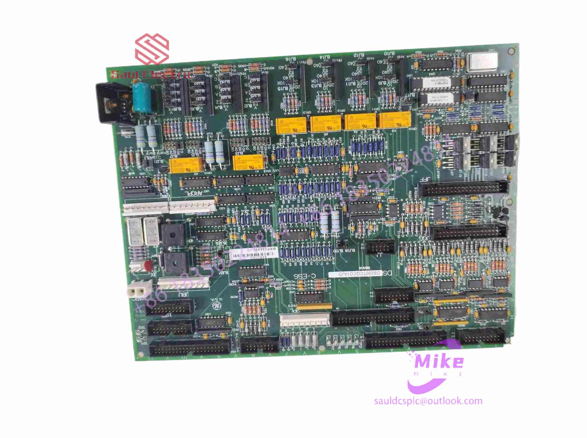
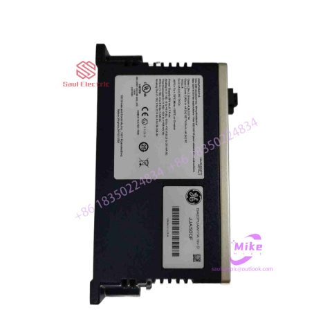
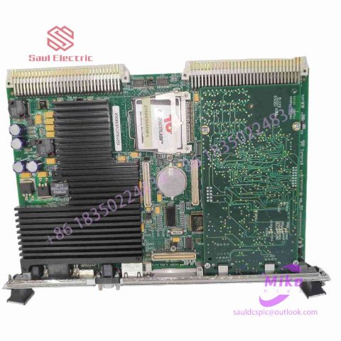
IS230TDBTH6A Turbine Control System
IS230TDBTH6A Product Introduction
Basic Information
Brand: GE (General Electric)
Model:IS230TDBTH6A
Part Number: IS230TDBTH6A
Series: Mark VIe Speedtronic Turbine Control System I/O Pack
Country of Origin: United States
Product Type: Discrete Input Module (Contact Input Module), also known as PDIA I/O Pack
contacts: Mike
+86 18350224834 (WeChat/WhatsApp)
Email:Mike18350224834@gmail.com
 Functional Overview
The IS230TDBTH6A is a 24-channel discrete (digital) input module in the GE Mark VIe control system. Its primary function is to collect discrete signals (contact open/close signals) generated by field devices such as sensors,
switches, and relays, convert them into digital signals that can be recognized and processed by the PLC or control system CPU,
and transmit the processed data to the GE Speedtronic turbine control system or other control equipment, enabling automated control and monitoring. Key Technical Specifications
Rated Voltage: 24.0 VDC (Nominal)
Maximum Rated Voltage: 28.6 VDC
Maximum Rated Contact Input Voltage: 32 VDC
Number of Input Channels: 24 Discrete Inputs
Operating Temperature Range: -30°C to +65°C
Environmental Adaptability: Passes rigorous environmental testing, capable of long-term stable operation in harsh industrial environments Compatible Terminal Boards
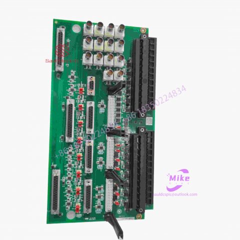
The IS230TDBTH6A can be paired with a variety of GE terminal boards, including but not limited to:
IS200STCIH1A / IS200STCIH2A
IS200STCIH8A
IS200TBCIH2C / IS200TBCIH4C
IS400STCIH1A / IS400STCIH2A / IS400STCIH8A
IS400TBCIH2C Certifications and Safety
This module is UL certified and can be used in both hazardous and non-hazardous locations. The UL certification covers various classes and divisions, and relevant UL mark documents are available for reference.
2. Principle of frequency converter
In embedded development, the control of motors is often involved. Currently, frequency conversion control of AC motors is widely used, so let’s briefly introduce the frequency converter by looking at the diagram, assuming that you already understand the principle of the motor.
The block diagram is as follows:
The frequency converter is mainly composed of rectifier (AC to DC), filtering, inverter (DC to AC), braking unit, drive unit, detection unit, microprocessing unit, etc. The inverter relies on the switching of the internal IGBT to adjust the voltage and frequency of the output power supply, and provides the required power supply voltage according to the actual needs of the motor, thereby achieving the purpose of energy saving and speed regulation. In addition, the inverter also has many protection functions. , such as overcurrent, overvoltage, overload protection, etc. With the continuous improvement of industrial automation, frequency converters have also been widely used.
A typical inverter system diagram is shown below. It mainly includes operation panel, VFD controller, motor and other parts.
1. Typical structure:
Mainly includes: control platform, measurement circuit, power circuit, protection circuit, etc.
There are two common types of frequency converters: voltage type and current type. Among them, the power inverter part mostly uses power tubes such as IGBT and IGCT.
2. Typical algorithm:
Among them, the control algorithm represented by Siemens is mainly based on coordinate transformation (vector control). Friends who are interested in the algorithm represented by ABB can search for information by themselves (direct torque control) and will not go into details here.
3. Vector control:
Many chip MCU and MPU manufacturers have provided block diagrams and algorithm libraries for variable frequency vector control. Those who are interested can study it. For example, the following figure is a block diagram provided by Microchip

There are no reviews yet.