
 HONG KONG SAUL

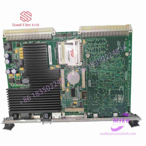
IS410TRLYS1D Turbine Control System
IS410TRLYS1D Product Introduction
Basic Information
Brand: GE (General Electric)
Model:IS410TRLYS1D
Part Number: IS410TRLYS1D
Series: Mark VIe Speedtronic Turbine Control System I/O Pack
Country of Origin: United States
Product Type: Discrete Input Module (Contact Input Module), also known as PDIA I/O Pack
contacts: Mike
+86 18350224834 (WeChat/WhatsApp)
Email:Mike18350224834@gmail.com
 Functional Overview
The IS410TRLYS1D is a 24-channel discrete (digital) input module in the GE Mark VIe control system. Its primary function is to collect discrete signals (contact open/close signals) generated by field devices such as sensors,
switches, and relays, convert them into digital signals that can be recognized and processed by the PLC or control system CPU,
and transmit the processed data to the GE Speedtronic turbine control system or other control equipment, enabling automated control and monitoring. Key Technical Specifications
Rated Voltage: 24.0 VDC (Nominal)
Maximum Rated Voltage: 28.6 VDC
Maximum Rated Contact Input Voltage: 32 VDC
Number of Input Channels: 24 Discrete Inputs
Operating Temperature Range: -30°C to +65°C
Environmental Adaptability: Passes rigorous environmental testing, capable of long-term stable operation in harsh industrial environments Compatible Terminal Boards
The IS410TRLYS1D can be paired with a variety of GE terminal boards, including but not limited to:
IS200STCIH1A / IS200STCIH2A
IS200STCIH8A
IS200TBCIH2C / IS200TBCIH4C
IS400STCIH1A / IS400STCIH2A / IS400STCIH8A
IS400TBCIH2C Certifications and Safety
This module is UL certified and can be used in both hazardous and non-hazardous locations. The UL certification covers various classes and divisions, and relevant UL mark documents are available for reference.
1.2 Five-wire resistive screen
The base layer of the five-wire resistance technology touch screen adds voltage fields in both directions to the conductive working surface of the glass through a precision resistor network. We can simply understand that the voltage fields in both directions are applied to the same working surface in a time-sharing manner. The outer nickel-gold conductive layer is only used as a pure conductor. There is a method of detecting the X-axis and Y-axis voltage values of the inner ITO contact point time-sharing after touching to measure the position of the touch point. The five-wire resistive touch screen requires four leads in the inner layer of ITO, and only one conductor in the outer layer. The touch screen has a total of 5 leads. Features: High resolution, high-speed transmission response. High surface hardness reduces abrasions, scratches and resists chemical treatments. It can still be used after 30 million contacts with the same point. Conductive glass is the base material. Once calibrated, it has high stability and will never drift. The five-wire resistive touch screen has the disadvantages of high price and high environmental requirements.
1. 3 Limitations of resistive screens
Whether it is a four-wire resistive touch screen or a five-wire resistive touch screen, they are a working environment that is completely isolated from the outside world. They are not afraid of dust and water vapor. They can be touched by any object and can be used to write and draw. They are more suitable for the field of industrial control. and limited-person use within the office. A common disadvantage of resistive touch screens is that because the outer layer of the composite film is made of plastic material, uninformed people may scratch the entire touch screen if they touch it too hard or use a sharp object, causing it to be scrapped. However, within limits, scratches will only damage the outer conductive layer. Scratches on the outer conductive layer do not matter for five-wire resistive touch screens, but are fatal for four-wire resistive touch screens.
2. Capacitive touch screen
2.1 Capacitive technology touch screen
It works by using the human body’s current induction. The capacitive touch screen is a four-layer composite glass screen. The inner surface and interlayer of the glass screen are each coated with a layer of ITO. The outermost layer is a thin layer of silica glass protective layer. The interlayer ITO coating serves as the working surface. Four electrodes are drawn out, and the inner ITO layer is a shielding layer to ensure a good working environment. When a finger touches the metal layer, due to the electric field of the human body, a coupling capacitance is formed between the user and the touch screen surface. For high-frequency current, the capacitance is a direct conductor, so the finger draws a small current from the contact point. This current flows out from the electrodes on the four corners of the touch screen, and the current flowing through these four electrodes is proportional to the distance from the finger to the four corners. The controller obtains the position of the touch point by accurately calculating the ratio of these four currents. .

There are no reviews yet.